Laser power regulating method based on model features

A technology of laser power and adjustment method, which is applied in processing and manufacturing, manufacturing tools, processing data acquisition/processing, etc., can solve the problems of small calculation amount and poor molding size accuracy, and achieve small calculation amount, high precision, and overcome the forming effect poor effect

Inactive Publication Date: 2018-01-19
HUAZHONG UNIV OF SCI & TECH
View PDF1 Cites 29 Cited by
  • Summary
  • Abstract
  • Description
  • Claims
  • Application Information

AI Technical Summary

Problems solved by technology

[0014] In view of the above defects or improvement needs of the prior art, the present invention provides a laser power adjustment method based on model features, in which, in view of the existing characteristics of poor molding dimension accuracy caused by heat accumulation in complex shape areas in existing laser printing, Corresponding studies have proposed and made full use of the method of slicing the workpiece model, and used the contour progressive method to fill the special area of ​​each slice layer, especially using the finite element to calculate the adjusted laser filling power. The whole process can Precisely control the laser filling rate of the special area in the part model, overcome the problems of poor forming effect of the existing internal complex structure forming part and difficult powder removal in post-processing, and effectively ensure the solid area in the laser local scanning process. The temperature of the melting pool during laser scanning is stable in the optimal melting temperature window range of powder materials, which improves the forming accuracy of the final formed part; and this method also has the advantages of small amount of calculation and easy operation, and is suitable for the 3D printing field of laser processing. Especially in SLS, SLM, SLA and other fields

Method used


Image

  • Laser power regulating method based on model features
  • Laser power regulating method based on model features
  • Laser power regulating method based on model features

Examples


Embodiment Construction

[0042] In order to make the object, technical solution and advantages of the present invention clearer, the present invention will be further described in detail below in conjunction with the accompanying drawings and embodiments. It should be understood that the specific embodiments described here are only used to explain the present invention, not to limit the present invention. In addition, the technical features involved in the various embodiments of the present invention described below can be combined with each other as long as they do not constitute a conflict with each other.

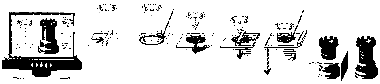
[0043] A laser power adjustment method based on model features, the flow diagram is as follows Figure 10 As shown, it specifically includes the following steps:

[0044] Step 1: The part model is voxelized first, and the voxels in the area containing complex structural features inside the model are marked, and all special spatial regions of the part model are obtained, and marked as V special...


PUM

PropertyMeasurementUnit
melting pointaaaaaaaaaa

Abstract

The invention belongs to the technical field of laser material additive manufacturing, and particularly relates to a laser power regulating method based on model features. The laser power regulating method comprises the following steps that a special region with a complex structure in a model is obtained, slicing processing is conducted on the workpiece model, and preprocessing is conducted on thesplice contour of a special region in the contour data of each layer, the laser power of the point needed to be adjusted is calculated point-by-point; and the slice contour of a non-special region ineach layer contour data is filled in a conventional filling mode; and the process is repeated until layer processing of all slices of the workpiece model is finished, and finally the laser printing path data of the workpiece model is generated. According to the laser power regulating method based on the model features, the heat accumulation effect generated by excessively intensive scanning and printing of in the local region of the laser is utilized, and the laser power of the progressive contour ring filling path in the region is adjusted dynamically, so that adverse effects caused by the heat accumulation effect is avoided, and the fact that the temperature of a material molten pool is stable in the melting temperature range of powder materials all the time is guaranteed.

Description

technical field [0001] The invention belongs to the technical field of laser additive manufacturing, and more specifically relates to a laser power adjustment method based on model features, which can overcome the problems of poor forming effect of existing internal complex structure forming parts and difficulty in powder removal in post-processing . Background technique [0002] Laser additive manufacturing technology is a kind of additive manufacturing technology. The laser with high energy density is irradiated on the liquid or powder material to change the properties of the material, and the laser is used in the physical area of ​​each layer of the workpiece model. The way of mobile scanning completes the overall manufacturing of the model layer by layer. The schematic diagram is as follows figure 1 shown. [0003] Laser additive manufacturing technology covers different types of manufacturing processes, such as selective laser sintering (Selective Laser Sintering, SLS...

Claims


Application Information

Patent Timeline
Patent Type & Authority Applications(China)
IPC IPC(8): B29C64/153B29C64/124B29C64/273B29C64/386B33Y10/00B33Y30/00B33Y50/00
Inventor 张李超张楠陈锦锋史玉升赵祖烨
Owner HUAZHONG UNIV OF SCI & TECH
Why Eureka
Try Eureka