Needle cylinders for circular knitting machines

A technology of circular weft knitting machine and needle cylinder, which is applied in the directions of knitting, weft knitting, textile and paper making, etc., can solve the problems of expensive, abnormal sharpness and mutual interference.

Active Publication Date: 2018-03-02
SANTONI SPA
View PDF7 Cites 0 Cited by
  • Summary
  • Abstract
  • Description
  • Claims
  • Application Information

AI Technical Summary

Problems solved by technology

This corrective operation is expensive and complicated and introduces other problems
In fact, although the precise external dimensions of the needle channel are required at the end of the operation, such a corrective operation on the outer surface would sharpen the outer surface of the rib (or partition): in other words, if the corrective operation , the edge between the side wall and the outer surface of the rib (or partition) can become exceptionally sharp and in fact become a "cutting" edge
[0010] Such sharp edges can cause a problem during the operation of the knitting machine: in fact, the needles and movement selectors located in the needle channel interfere with each other with the sharp edges formed between said side wall and said outer surface; For example, the needle "pulls" on said edge during its raising or lowering motion
Interference or contact between this needle and the edge of the needle channel can cause material to be removed from the needle
This is a disadvantage of increased wear on the needles and furthermore said removed material is placed on the knitting machine and contaminates the lubricating oil on the needle cylinders
To limit the effects of such sharp edges, the barrel is "run-in" by rotating it around itself at a slow rate (compared to normal operating speed) for days or weeks: The sharp edge cuts into the beveled edge, but this creates a loss of time during which production cannot take place, and in either case does not prevent damage or wear to the needle during the "run-in" period
[0011] In either case, in the prior art (especially in solutions using syringes incorporating partitions) the rib or the diameter of the outer surface of the partition wall is impossible to have exact dimensions

Method used


Image

  • Needle cylinders for circular knitting machines
  • Needle cylinders for circular knitting machines
  • Needle cylinders for circular knitting machines

Examples


Embodiment Construction

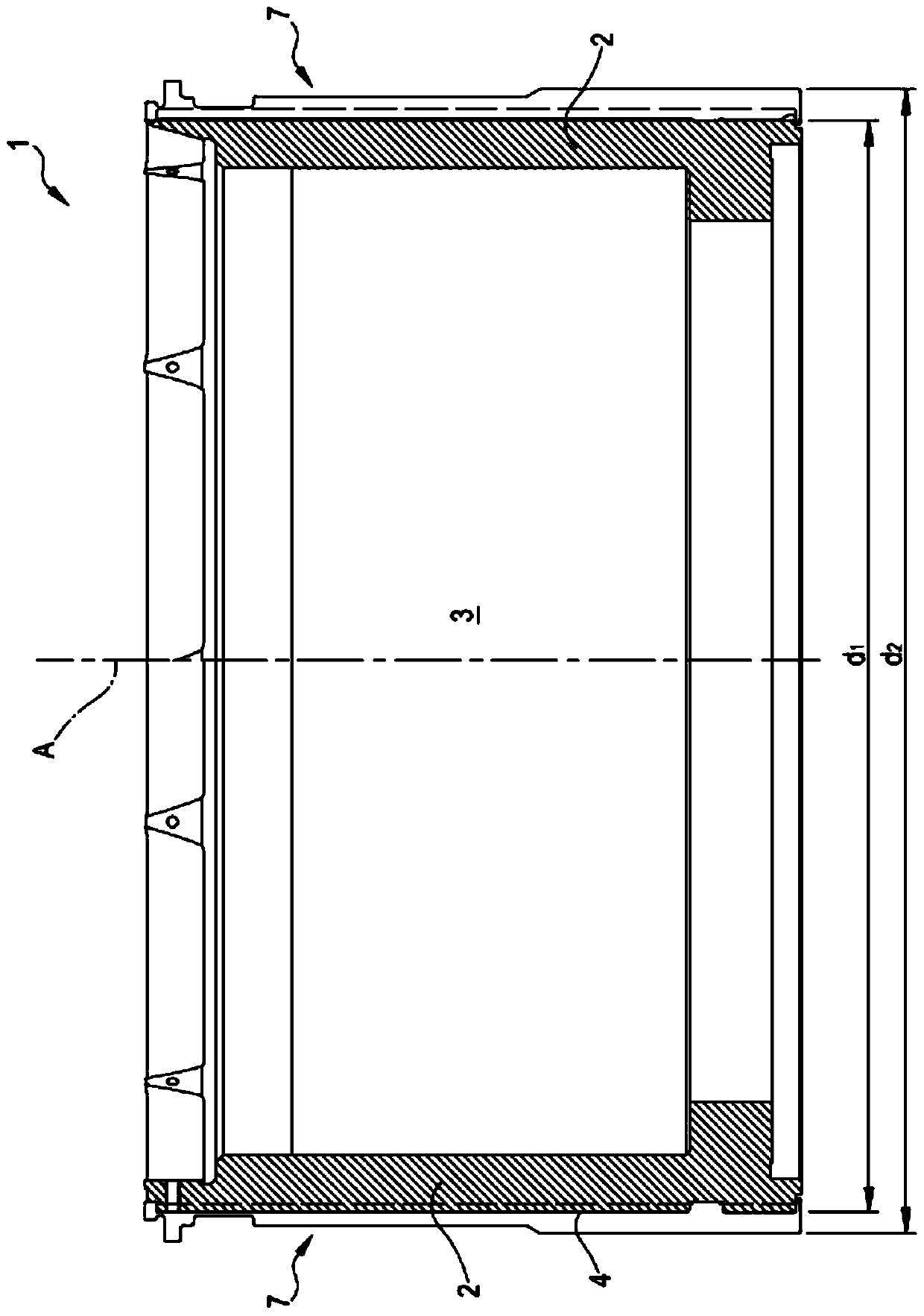
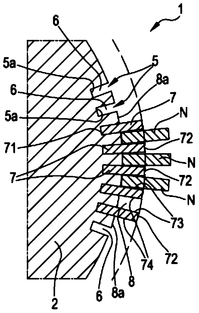
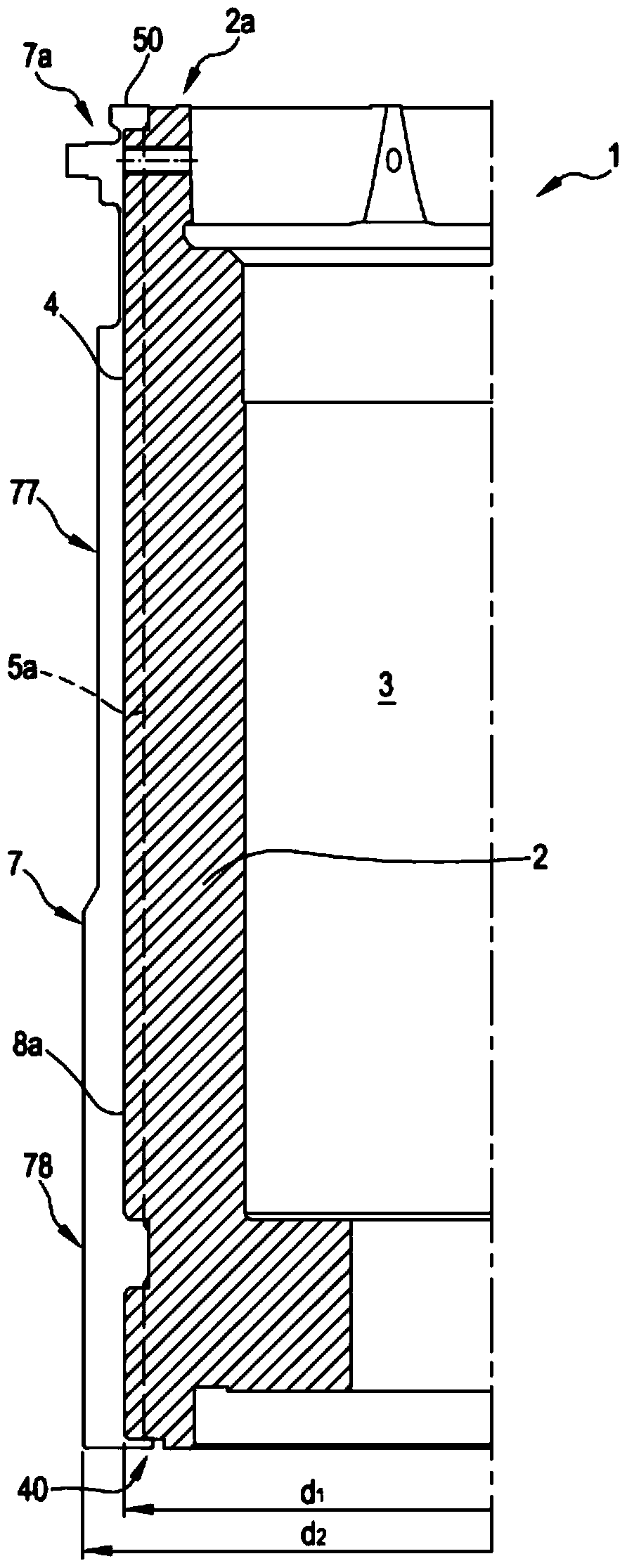
[0098] With reference to the above-mentioned figures, reference numeral 1 denotes the entire cylinder for a circular knitting machine according to the present invention. In general, the same reference numbers are used for the same or similar elements, even if these elements are present in different embodiments.

[0099] figure 1 A possible embodiment of a cylinder according to the invention for a circular knitting machine with some parts removed is shown. In particular, the description of the knitting machine focuses on the cylinder and the elements connected to the cylinder (especially the partition wall), and the description of the knitting machine facilitates the understanding of the present invention. The base of the knitting machine, the control elements of the knitting head, the part containing the central processing unit and other parts of the knitting machine are not shown in detail, since these are of known and conventional type. From the perspective of knitting tec...


PUM


Abstract

A needle cylinder (1) for a circular knitting machine for knitwear or hosiery, comprising a cylinder body (2) provided with an external surface (4) and with a plurality of vertical slots (5) made in the external surface, wherein the plurality of slots realize a corresponding plurality of seatings (6). The cylinder comprises a plurality of vertical beams, or walls (7), each wall having a prevalent longitudinal development and being positionable in a respective seating (6). Each pair of adjacent walls (7) defines a needle channel (8), corresponding to a vertical space comprised between the adjacent walls; the needle channel is configured for movably housing a respective needle. The body (2) is further provided with a first annular niche (10) extending in circular fashion about the external surface (4). At least one of the walls exhibits at least a respective first protuberance (11) configured to insert in a respective angular portion of the first niche (10).

Description

technical field [0001] The invention relates to a cylinder for a circular knitting machine, in particular for knitwear or hosiery. The invention also relates to a method of realizing a needle cylinder for a circular knitting machine. The present invention relates to the technical field of circular knitting machines for knitwear, seamless knitwear, hosiery and the like. Background technique [0002] Circular knitting machines have needle support elements called "cylinders". The needle cylinders are mounted to the stationary structure (or floor frame) of the circular knitting machine and are rotatable about their own central axis. The barrel also has a plurality of "needle channels" (ie, vertical bases), parallel to the central axis of the barrel, present on the outer surface of the barrel and extending around the entire barrel. Each needle channel removably houses a corresponding needle of the knitting machine so that said needles can be selectively moved within each needl...

Claims


Application Information

Patent Timeline
Patent Type & Authority Patents(China)
IPC IPC(8): D04B15/14
CPCD04B15/14
Inventor E·洛纳蒂F·洛纳蒂
Owner SANTONI SPA
Why Eureka
Try Eureka