Drilling system and method based on subsea pump pressure control

A subsea pump and drilling technology, which is applied in underwater drilling, wellbore/well parts, earthwork drilling and production, etc., can solve the problems of high cost of drilling rig equipment, poor economic benefits, and consumption, and achieve a narrow pressure window and reduce drilling costs. cost, effect of expanding density range

Active Publication Date: 2015-07-08
CHINA NAT OFFSHORE OIL CORP +1
View PDF5 Cites 17 Cited by
  • Summary
  • Abstract
  • Description
  • Claims
  • Application Information

AI Technical Summary

Benefits of technology

This patented technology solves problems associated with traditional methods used during oil exploration operations like drills or pipelines. It includes several technologies including drill rods, drill bits attached to them, an underground tank filled with water called seawater, a submersonic (submersible) propulsion unit located below ground, a hydrostatic head elevator mechanism, a subsidiary pumping station, a combination of these components, and various sensors placed close enough proximity to each component to detect any harmful gases entering the borehole while also controllably driving downward movement of the tool towards deeper areas without causing damage.

Problems solved by technology

The technical problem addressed by this patented method relating to controlling the flow of gases during oil field development involves finding ways for efficient use of resources while also addressing issues like environmental concerns caused by excessive amounts of methanol (MeOH) released from traditional methods that involve burning off hydrocarbon fuel beforehand.

Method used


Image

  • Drilling system and method based on subsea pump pressure control

Examples


Embodiment Construction

[0013] The present invention will be described in detail below in conjunction with the accompanying drawings and embodiments.

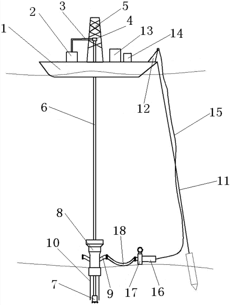
[0014] Such as figure 1 As shown, the present invention proposes a drilling system based on subsea pump pressure control, the system includes a drilling ship 1 arranged on the sea surface, a drilling fluid supply device 2 is arranged on the drilling ship 1, and the drilling fluid supply device 2 passes through A liquid manifold 3 is connected to a liquid inlet end of a faucet 4 . A derrick 5 is fixedly connected to the middle part of the drilling ship 1, and the swivel 4 is fixedly connected to the derrick 5. The liquid outlet end of the swivel 4 is rotatably connected to the top of a drill pipe 6, and a drill bit 7 is fastened to the bottom of the drill pipe 6. 6 rotates under the drive of a motor (not shown) fixedly connected on the derrick 5. A suction module 8 is sleeved on the bottom of the drill pipe 6, and the bottom of the suction module 8 i...


PUM


Abstract

The invention relates to a drilling system and method based on subsea pump pressure control. The system is characterized by comprising a drilling ship; a drilling liquid supplying device and a control device are arranged on the drilling ship; the drilling liquid supplying device is connected with the liquid feeding end of a water faucet through a liquid manifold; the water faucet is fixedly connected to a derrick arranged in the middle part of the drilling ship; the liquid discharging end of the water faucet is in rotating connection with the top end of a drilling rod; a drill bit is fixedly connected to the bottom end of the drilling rod; an absorbing module sleeves the lower part of the drilling rod; two pipelines are symmetrically arranged on the outer pipe wall of the absorbing module; a throttle valve is arranged on the pipeline at one side; the control device is electrically connected to an electrical device positioned on the drilling ship; the electrical device is electrically connected with a motor through a control and power pipeline; the output end of the motor is connected with a subsea pump; an inlet of the subsea pump is connected with a hose and provided with a pressure flow sensor. According to the system, the opening degree of the throttle valve and the rotating speed of the subsea pump can be adjusted by a control panel device through the control and power pipeline, so that the pressure of a wellhead of a subsea drilling well is stable, and as a result, the well control risk caused by natural gas-water composition can be controlled.

Description


Claims


Application Information

Patent Timeline
Owner CHINA NAT OFFSHORE OIL CORP
Why Eureka
Try Eureka