Fuel jet method

A fuel and nozzle technology, applied in the direction of fuel injection device, fuel injection control, charging system, etc., can solve the problems of incomplete combustion and large number of combustion chambers

Inactive Publication Date: 2008-09-03
WAERTSILAE SWITZERLAND
View PDF1 Cites 0 Cited by
  • Summary
  • Abstract
  • Description
  • Claims
  • Application Information

AI Technical Summary

Problems solved by technology

[0003] The disadvantage of this injection method is that incomplete combustion occurs in the combustion chamber especially when operating at part load, so that the combustion exhaust has a large amount of visible smoke

Method used


Image

  • Fuel jet method
  • Fuel jet method
  • Fuel jet method

Examples


Embodiment Construction

[0028] In the following text, the working cycle is understood to mean the processes that occur during the operation of a reciprocating piston internal combustion engine, including valve actuation, combustion injection, combustion and discharge of combustion gases. In two-stroke machines, the working cycle is usually It is done between two revolutions in a four-stroke machine.

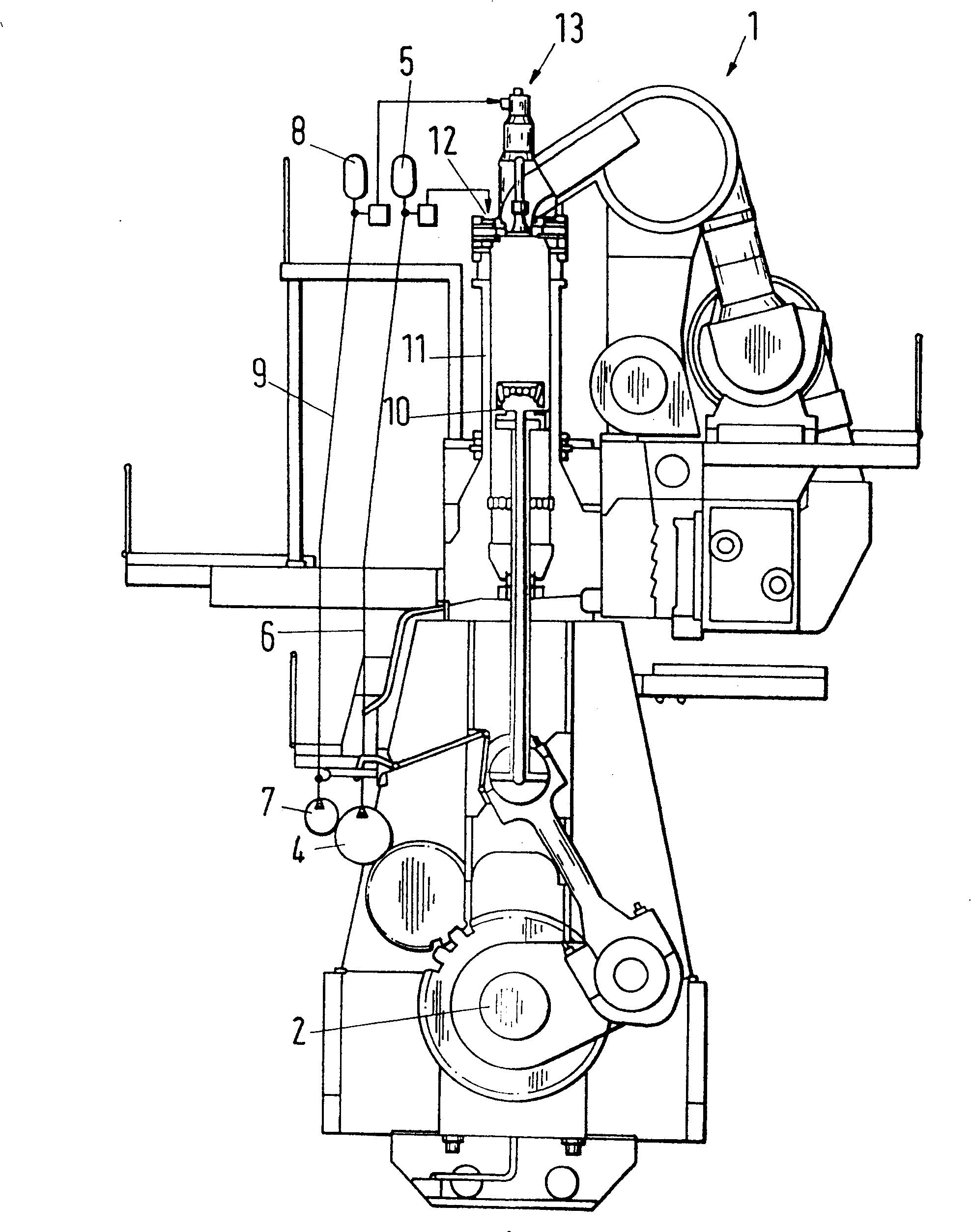
[0029] figure 1 A two-stroke diesel engine 1 is shown, with several cylinders 11 and pistons 10, wherein the interaction between the crankshaft 2, the combustion delivery and the movement of the exhaust valves 13 is electronically controlled. Fuel is delivered to the nozzles 12 by means of a high-pressure pump 4 via the line 6 and the pressure accumulator 5 . The hydraulic system comprising the pressure pump 7 , the pipeline 9 and the pressure accumulator 8 allows the positioning of the actuated exhaust valve 13 . The exhaust valve 13 and several nozzles 12 arranged in the center of the longitudinally...


PUM


Abstract

Method for injecting fuel (14a) into a combustion chamber having at least two fuel injectors (12a, 12b, 12c) of a cylinder (11) of a reciprocating internal combustion diesel engine in underload operation comprises alternately injecting the fuel so that during at least two successive working cycles no fuel is injected by at least one of the fuel injectors and during at least two following successive working cycles no fuel is injected by the other fuel injector. An Independent claim is also included for a reciprocating internal combustion engine operated by the method. Preferred Features: Each combustion chamber has two, three or four fuel injectors.

Description

technical field [0001] The present invention relates to a method for injecting fuel into a combustion chamber in a cylinder of a reciprocating piston diesel engine during partial load operation. Background technique [0002] From the specification EP 0 775 821 a method is known for injecting fuel into a combustion chamber in a cylinder of a low speed reciprocating piston diesel engine. Fuel is injected into the combustion chamber using two to four fuel nozzles which operate continuously over the entire load range. Especially during partial load operation, the specified fuel quantity is injected by only one nozzle in one power stroke, and in the next power stroke, the specified fuel quantity is injected by the second nozzle, therefore, in each power stroke, the The required amount of fuel is injected alternately from each nozzle. [0003] The disadvantage of this injection method is that incomplete combustion occurs in the combustion chamber, especially during partial load ...

Claims


Application Information

Patent Timeline
Patent Type & Authority Patents(China)
IPC IPC(8): F02D41/30F02B23/02F02D41/02F02D41/04F02F1/24F02M61/14F02M63/00
CPCY02T10/125F02F1/242F02M61/14F02M63/00
Inventor K·黑姆T·海尼A·比特利
Owner WAERTSILAE SWITZERLAND
Why Eureka
Try Eureka