Small gas turbine engine with multiple burn zones

a gas turbine engine and burn zone technology, applied in the ignition of turbine/propulsion engine, engine starter, engine, etc., can solve the problem that a combustion engine is not practical in a small, compact gas turbin

Inactive Publication Date: 2009-08-04
FLORIDA TURBINE TECH
View PDF14 Cites 18 Cited by
  • Summary
  • Abstract
  • Description
  • Claims
  • Application Information

AI Technical Summary

Benefits of technology

[0019]The combustor includes two burn zones, a primary burn zone located in an aft portion of the combustor and a secondary burn zone located in a rearward portion of the combustor, the two burn zones providing for maximum combustor output in a given small volume. The primary zone is designed for maximum residence time and recirculation, and is responsible for engine ignition and lean stability. The secondary zone is designed for maximum efficiency of the combustor at full power operation and during starting. The secondary zone can be designed to aid in ignition if desired, but its main function is to complete combustion of fuel that does not burn in the primary zone. The secondary zone allows for the primary zone to operate at fuel-rich conditions since it provides air and re-circulation for complete burning. This arrangement is critical for small engines used in missiles or UAVs in order to minimize installation volume requirements while providing adequate engine throttle ability without flame-out. Also, a larger combustor can have enhanced stability and / or lower emissions using the two burn zones.
[0021]The rotary cup fuel injection provides for fine fuel atomization for easy ignition as well as efficient and clean burning. The rotary cup lip diameter and rotational speed provide for droplet sizes well below those required for ignition, even at low speed (<7% of full speed) and with cold or viscous fuels. The rotary cup also allows for fuel injection to occur through a single, relatively large passage or tube, making it resistant to coking, plugging, or fouling. The rotary cup allows for fuel injection into both the primary and secondary burn regions and zones, either simultaneously or in stages in order to maximize combustor operating range and efficiency. Fuel atomization for unassisted cold ignition is one of the key benefits of the rotary cup atomization system. Reliable ignition and rapid acceleration without the need for expensive and heavy start assist systems and ignition systems is possible because of the rotary cup injector. Improved low speed efficiency for faster, more reliable, starting, and lower cruise-speed fuel burn is another advantage.
[0023]The rotary cup may have vanes or radial grooves to aid in swirling combustor internal flow. Since the rotary cup surface speeds are high, a great deal of swirl can be imparted to the flow entering the combustor without losing pressure in a way that reduces overall engine efficiency.
[0024]The rotary cup accommodates incorporation of a shaft fuel pump. In this case, fuel would enter the engine through a hole down the center of the shaft, pass to the rotary cup, and get pumped to high pressure via shaft rotation as it passes into the combustor through a set of small radial holes. This allows the engine fuel pump to be significantly smaller, lower cost and to be more precise with respect to fuel metering.
[0025]Ignition is achieved via a single igniter at the outer combustor wall. The rotary cup sprays fuel directly toward the igniter where there is an air flow stagnation point, ideal for ignition. By properly locating the igniter, ignition may be achieved in the primary, secondary, or both burn zones. This provides a wider range of fuel and air ratios at which ignition can occur, resulting in the widest possible engine relight envelope. The combustor also has few parts, requiring only one igniter, one to four fuel injection tubes, simple and plain holes, and a small number of sheet metal components. This provides for a reliable, producible, and low cost system.

Problems solved by technology

In the Szydlowski, Melconian, and Heitmann inventions discussed above, all three of these combustors suffer from the same problem: combustion space is large in order to provide the required space to allow for enough fuel to burn to generate the gas stream for the engine.
Therefore, the combustor would not be practical in a small, compact gas turbine engine used in a UAV.

Method used


Image

  • Small gas turbine engine with multiple burn zones
  • Small gas turbine engine with multiple burn zones
  • Small gas turbine engine with multiple burn zones

Examples


Embodiment Construction

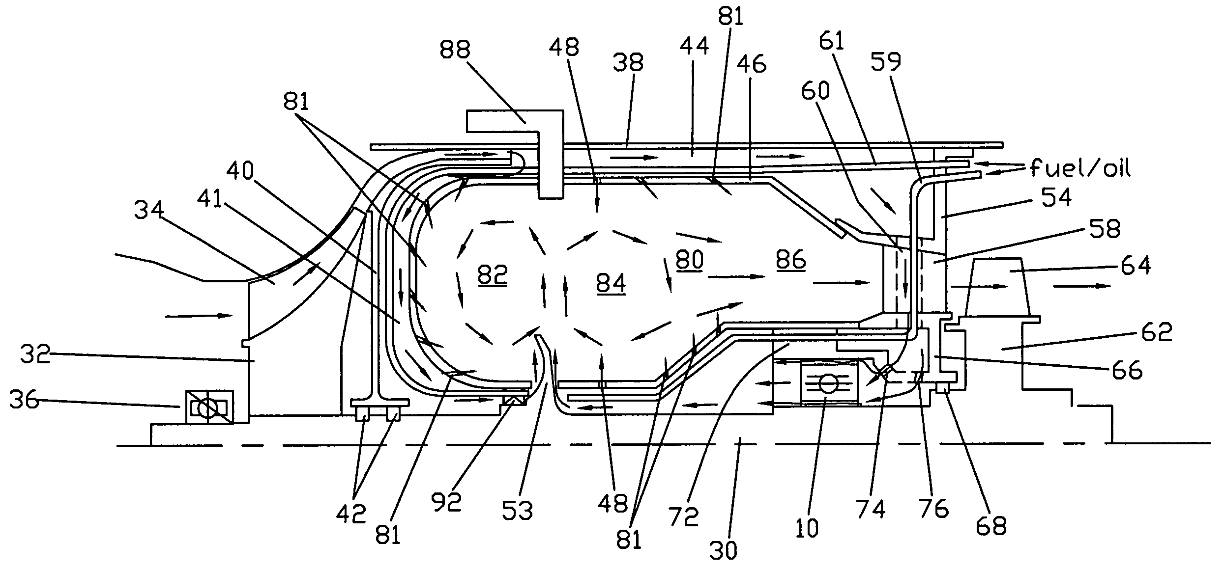
[0032]The present invention is a small gas turbine engine primarily used in Unmanned Arial Vehicles (UAV) such as a small cruise missile in which a rear bearing used to support the rotor shaft and located in the hot section of the turbine is cooled with cooling air diverted from the compressor, the cooling air passing through the bearing inner and outer races to maintain the races at similar temperatures to prevent radial clearance from developing in the bearing, the cooling air then being discharged into the combustor to be burned with fuel. A rotary cup fuel injector is used to inject fuel into the combustor, the combustor being separated into a primary burn zone located aft in the combustor and a secondary burn zone located downstream from the primary burn zone. The rotary cup fuel injector injects fuel into both burn zones to promote a swirl flow within the respective burn zones in order to promote full burning of the fuel. Compressed air supplied from the compressor passes over...


PUM


Abstract

A small gas turbine engine for use in an UAV such as a cruise missile, the gas turbine having a combustor forming a primary burn zone and a secondary burn zone, and in which fuel is injected into both the primary and the secondary burn zones by either a rotary cup injector or a plurality of fuel injector nozzles. The secondary burn zone with separate fuel injection allows for the diameter of the engine to be reduced in size but still allow for adequate power and efficiency to be reached for powering the vehicle. Air flow from the compressor is used to cool the combustor walls before being injected into the combustor, and to pass through and cool the guide nozzles and a main bearing located near the hot section of the combustor prior to being introduced into the combustor.

Description

GOVERNMENT LICENSE RIGHTS[0001]This invention was made with Government support under Contract No. W31P4Q-05-C-R003 awarded by the US Army. The Government has certain rights in the invention.BACKGROUND OF THE INVENTION[0002]1. Field of the Invention[0003]The present invention relates to small, compact and expendable gas turbine engine having rotary cup fuel injector with two burn zones.[0004]2. Description of the Related Art Including Information Disclosed Under 37 CFR 1.97 and 1.98[0005]Small gas turbine engines of the kind used in Unmanned Air Vehicles (UAV) such as a small cruise missile are well known in the art. These turbines produce a thrust from less than 300 lbs to several hundred lbs. Because these turbine engines must fit within a small space, they tend to be very compact. Since the engine must be compact in size, the combustor must be as small as possible. However, the combustor must provide a long enough burn path to remain lit, and to burn the fuel to produce power with...

Claims


Application Information

Patent Timeline
Patent Type & Authority Patents(United States)
IPC IPC(8): F02C3/00
CPCF01D25/12F02C3/14F23R3/38F02C7/22F05D2250/80
Inventor HARRIS, MARK M.BROWN, WESLEY D.GARCIA, ANGEL M.
Owner FLORIDA TURBINE TECH
Why Eureka
Try Eureka