
Circuit Breaker Trip Structure

A circuit breaker and tripping technology, which is applied in the field of circuit breaker tripping structure, can solve the problems of inability to guarantee forced closing, inability to ensure safety due to arrears and electricity theft, and achieve the effect of ensuring safety and preventing arrears and electricity theft

Active Publication Date: 2017-06-16
SUZHOU FUTURE ELECTRICAL APP
View PDF2 Cites 0 Cited by
  • Summary
  • Abstract
  • Description
  • Claims
  • Application Information

AI Technical Summary

Problems solved by technology

This technical solution also cannot guarantee that it can prevent artificial forced closing when the fault is not resolved or the fee is not paid after a trip caused by a serious fault or arrears, so that it cannot ensure safety or prevent arrears from stealing electricity

Method used


Image

  • Circuit Breaker Trip Structure
  • Circuit Breaker Trip Structure
  • Circuit Breaker Trip Structure

Examples


Embodiment Construction

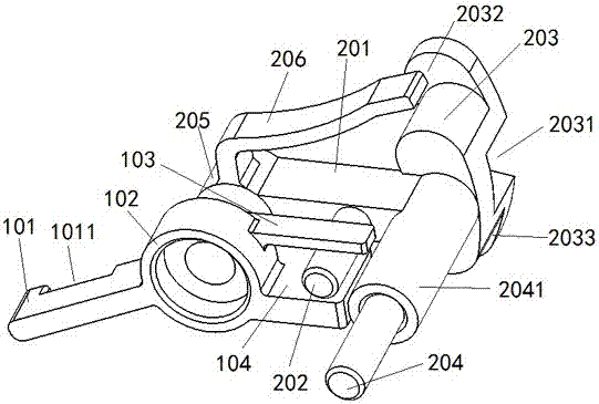
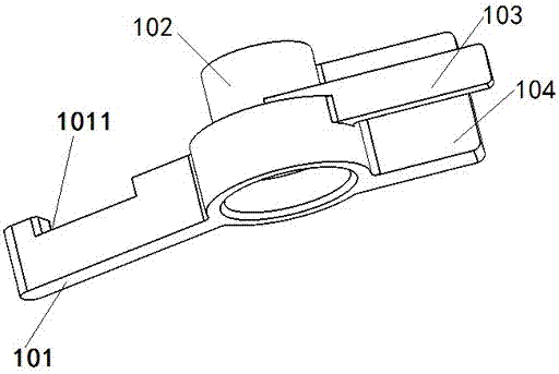
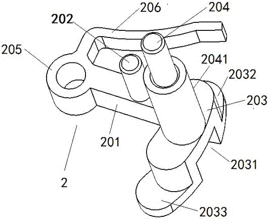
[0032] Such as Figure 1~6 As shown, the tripping structure of the circuit breaker is installed in the housing 3 of the electric control operator; the tripping structure of the circuit breaker includes a tripping driving part 1 and a tripping rotary part 2; the tripping driving part 1 and the tripping rotary part 2 have shaft holes and have the same axis center, and the tripping driving part 1 and the tripping rotary part 2 are movably connected through a fixed shaft; One side of the sleeve 102 extends laterally with a drive rod 101; the drive rod 101 has a second groove 1011, the second groove 1011 is square, and the trip driver 1 is provided with a first shaft sleeve 102 extending in the axial direction, and the trip The other side of the driving member 1 and the first sleeve 102 jointly extend in the transverse direction with a first clamping piece 103 and a second clamping piece 104; there is a rotation between the first clamping piece 103 and the second clamping piece 104...


PUM


Abstract

The invention discloses a circuit breaker tripping structure. The circuit breaker tripping structure comprises a tripping driving part and a tripping rotating part; the tripping driving part and the tripping rotating part are both provided with shaft holes and have the same axis, and the tripping driving part is movably connected with the tripping rotating part through a fixing shaft; the tripping driving part extends in the axial direction to be provided with a first shaft sleeve, and one side of the first shaft sleeve extends in the transverse direction to be provided with a driving rod; the other side of the tripping driving part and the first shaft sleeve jointly extend in the transverse direction to be provided with a first clamping part and a second clamping part; the tripping rotating part extends in the transverse direction to be provided with a platform, the platform is provided with a rotating rod in the axial direction, and the rotating rod is embedded between the first clamping part and the second clamping part; the tripping rotating part comprises a rotating portion, the rotating portion is provided with a connecting shaft in the axial direction, the connecting shaft is provided with a connecting shaft sleeve which is connected to the connecting shaft in a sleeving mode, and the connecting shaft sleeve is connected with the platform. The circuit breaker tripping structure can enable a circuit breaker to be quickly tripped and not be switched on through a handle.

Description

technical field [0001] The invention relates to the technical field of electrical switches, in particular to a circuit breaker tripping structure. Background technique [0002] Miniature circuit breaker, referred to as MCB, is the most widely used terminal protection device in electrical terminal distribution devices. It is used for single-phase and three-phase short-circuit and overload protection below 125A, including single-pole 1P, two-pole 2P, Three-pole 3P, four-pole 4P. The circuit breaker tripping structure is used to control the rapid tripping of the circuit breaker at a long distance, and the circuit breaker tripping structure usually adopts an electromagnet operating mechanism. The motor operating mechanism is used to operate the opening and closing of the circuit breaker. The closing and opening are achieved by the position of the cam inside the electric operating mechanism. When the circuit breaker is operated by the electric mechanism, it can ensure that the c...

Claims


Application Information

Patent Timeline
Patent Type & Authority Patents(China)
IPC IPC(8): H01H71/12
CPCH01H71/12
Inventor 毛海峰楼铭达
Owner SUZHOU FUTURE ELECTRICAL APP
Learn More