Opposite friction and drag reduction inertial piezoelectric motor and its control method and scanning probe microscope

A technology of piezoelectric motors and piezoelectric scanning tubes, applied in the field of piezoelectric positioners and scanning probe microscopes, can solve the problems of small output thrust of inertial piezoelectric motors, reduce static grip friction, etc., and achieve large thrust and restraint Effects of thermal drift, size reduction

Active Publication Date: 2017-07-07
合肥中科微力科技有限公司
View PDF1 Cites 0 Cited by
  • Summary
  • Abstract
  • Description
  • Claims
  • Application Information

AI Technical Summary

Problems solved by technology

[0005] The purpose of the present invention is to solve the problem of small output thrust of the inertial piezoelectric motor, and to propose a controllable reduction of the frictional resistance when the motor is walking by using opposite friction without reducing the static gripping friction force, thereby improving Inertial piezoelectric motor for outputting thrust, its control method and mirror body of scanning probe microscope made of it

Method used


Image

  • Opposite friction and drag reduction inertial piezoelectric motor and its control method and scanning probe microscope
  • Opposite friction and drag reduction inertial piezoelectric motor and its control method and scanning probe microscope
  • Opposite friction and drag reduction inertial piezoelectric motor and its control method and scanning probe microscope

Examples


Embodiment 1

[0033] Embodiment 1: Basic type opposite friction and drag reduction inertial piezoelectric motor

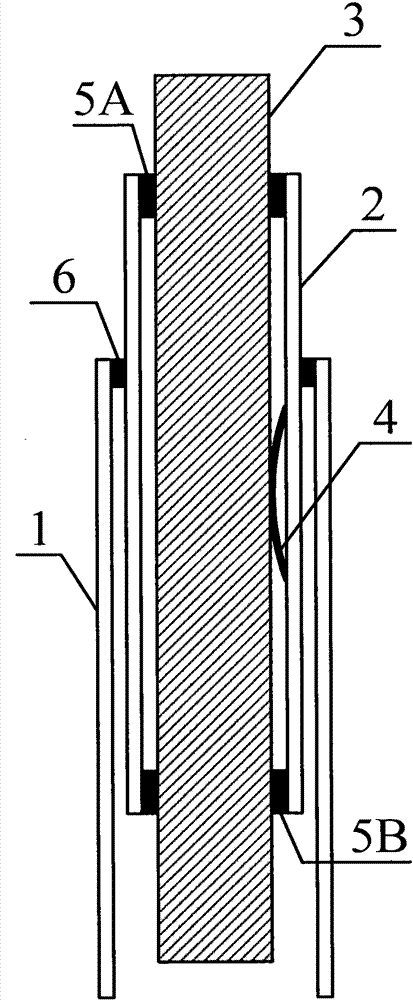
[0034] See attached figure 1 , the present invention's basic inertial piezoelectric motor with friction and resistance reduction includes: a driving piezoelectric body 1, a slide bar 3, and a spring leaf 4, and is characterized in that it also includes an auxiliary piezoelectric body 2, and the spring leaf 4 connects the slide bar 3 The two ends of the piezoelectric body 2 and the deformed two ends of the auxiliary piezoelectric body 2 are elastically pressed 5A, 5B to form a parallel mutual pressure structure. This end is called a free end, and the other end driving the piezoelectric body 1 is called a fixed end.

[0035] When working, let the auxiliary piezoelectric body 2 not deform and drive the piezoelectric body 1 to deform slowly. The inertial force generated by the slow deformation is smaller than the maximum static friction force between the auxiliary piezoelectric bod...

Embodiment 2

[0037] Embodiment 2: Drive slider type opposite friction and drag reduction inertial piezoelectric motor

[0038] attached figure 1 The free end of the driving piezoelectric body 1 is fixed with the auxiliary piezoelectric body 2, which is the case where the driving piezoelectric body 1 drives the auxiliary piezoelectric body 2, but the free end of the driving piezoelectric body 1 can also be connected with the slider 3 is fixed, this is the case where the driving piezoelectric body 1 drives the slide bar 3, at this time, the walking part is the auxiliary piezoelectric body 2, not the slide bar 3.

Embodiment 3

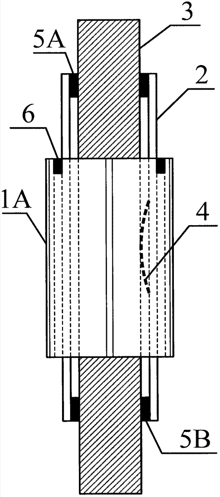
[0039] Embodiment 3: Tubular opposite friction and drag reduction inertial piezoelectric motor

[0040] Both the driving piezoelectric body 1 and the auxiliary piezoelectric body 2 in the above embodiment are tubular, the slider 3 is inserted into the auxiliary piezoelectric body 2, and the spring piece 4 is located between the slider 3 and the auxiliary piezoelectric body 2. Between the inner walls, the auxiliary piezoelectric body 2 is fixed to the free end of the driving piezoelectric body 1 . This structure has a high symmetry, which reduces thermal drift.


PUM


Abstract

The inertial piezoelectric motor, control method and scanning probe microscope of the present invention include a driving piezoelectric body, a slide bar, and a spring sheet, and are characterized in that they also include an auxiliary piezoelectric body, and the spring sheet connects the two sides of the slide bar. The end and the deformed two ends of the auxiliary piezoelectric body are elastically pressed together, and the auxiliary piezoelectric body or slide bar is fixed to one end of the deformed two ends of the driving piezoelectric body. When the motor is at rest, the gripping force on the slide bar is a large static friction force, the motor has strong anti-interference ability and high stability; The friction resistance decreases, and at this time, a large part of the inertial force generated by the rapid deformation of the driving piezoelectric body is transferred to the output thrust, and the motor steps powerfully. The present invention retains the advantages of simple structure, high precision, large working temperature range, and low processing precision requirements of the inertial piezoelectric motor, but solves its shortcomings of low rigidity, low compactness, and small output thrust, and is suitable for low temperature, ultrahigh Work under extreme conditions such as vacuum and strong magnetic field.

Description

technical field [0001] The invention relates to an inertial piezoelectric motor for reducing resistance by opposing friction, its control method and a scanning probe microscope, and relates to an inertial piezoelectric motor that utilizes opposing friction to effectively and controllably reduce resistance, its control method, and a device made of the same The invention relates to a scanning probe microscope, which belongs to the technical fields of piezoelectric positioners and scanning probe microscopes. Background technique [0002] Piezoelectric motor is a piezoelectric positioner that can simultaneously achieve high positioning accuracy on the order of nanometers or even sub-nanometers and macro strokes above millimeters or even centimeters. It is usually realized by using repeated piezoelectric deformation to generate cumulative displacement. It has the advantages of small volume and high positioning accuracy, so it is widely used in precision instrument control, atomic...

Claims


Application Information

Patent Timeline
Patent Type & Authority Patents(China)
IPC IPC(8): H02N2/02H02N2/06G01Q70/02
Inventor 陆轻铀
Owner 合肥中科微力科技有限公司
Why Eureka
Try Eureka