Eureka AIR delivers breakthrough ideas for toughest innovation challenges, trusted by R&D personnel around the world.

Lifting type flow-adjustable valve

A lift-type, flow-rate technology, applied in sliding valves, valve devices, engine components, etc., can solve the problems of poor control flexibility, no lift adjustment function, no flow control function, etc., and achieve the effect of convenient fine-tuning and convenient control.

Inactive Publication Date: 2015-07-15
SUZHOU FURUN MACHINERY
View PDF8 Cites 7 Cited by
  • Summary
  • Abstract
  • Description
  • Claims
  • Application Information

AI Technical Summary

Benefits of technology

This technology allows for easy adjustment of the heights at which two doors open up when they are closed on top of each other. By moving one gate towards another with an elevator mechanism, this makes it easier to finely tunes the size of pipes being transported through them.

Problems solved by technology

This patented describes different ways for controllers that use valving components like cutting off, regulation, flow divergence, reversal protection, pressure stability, flow directionality, and others. However, current designs lack both these features and their ability to perform more precise movements over time due to limitations associated with actuators themselves.

Method used


Image

  • Lifting type flow-adjustable valve

Examples


Embodiment Construction

[0012] In order to make the technical means, creative features, goals and effects achieved by the present invention easy to understand, the present invention will be further described below in conjunction with specific embodiments.

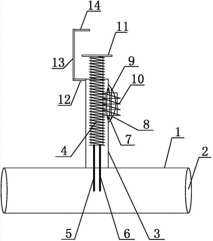
[0013] Such as figure 1 As shown, a lifting flow adjustable valve includes a pipe body 1, the pipe body 1 is a tubular structure, the two ends of the pipe body 1 are provided with outlets 2, the pipe body 1 is provided with a guide pipe 3, and the guide pipe 3 and the pipe The body 1 is arranged in a T-shape, the guide pipe 3 communicates with the pipe body 1, the guide pipe 3 is set with a lifting thread column 4, the outer surface of the lifting thread column 4 is provided with external threads, and the lower end of the lifting thread column 4 is provided with a first The lifting door panel 5 and the second lifting door panel 6, the first lifting door panel 5 and the second lifting door panel 6 are sheet-like structures, the first lifting door p...


PUM


Abstract

The invention discloses a lifting type flow-adjustable valve. The lifting type flow-adjustable valve comprises a pipeline body, wherein a guide tube is arranged on the pipeline body; a lifting threaded stud is arranged in the guide tube in a sleeving mode; a lifting door plate is arranged at the lower end of the lifting threaded stud, and the lifting door plate is arranged in the pipeline body; an open slot is formed in the side wall of the pipeline body, a connecting rod is connected on the side wall of the pipeline body, the connecting rod is provided with a guide rod, a rotary column is arranged on the guide rod in the sleeving mode, and the rotary column is in threaded and engaged connection with the lifting threaded stud. According to the lifting type flow-adjustable valve disclosed by the invention, the lifting door plate can be used for controlling the pipeline body to be opened or closed, and the rotary column can rotate to control the lifting threaded stud to realize vertical lifting, so that the lifting door plate can be controlled to realize vertical lifting, the flow of the pipeline body is conveniently fine-tuned, and the pipeline body is conveniently controlled.

Description


Claims


Application Information

Patent Timeline
Owner SUZHOU FURUN MACHINERY
Why Eureka
Eureka Blog
Learn More