Safe and reliable community security system

A security system and reliable technology, applied in the direction of supporting machines, mechanical equipment, machines/supports, etc., can solve the problems of dead ends in monitoring and easy detection of monitoring equipment, and achieve the effect of avoiding damage

Inactive Publication Date: 2015-07-15
MIANYANG HAOMAI ELECTRONICS SCI & TECH CO LTD
View PDF4 Cites 8 Cited by
  • Summary
  • Abstract
  • Description
  • Claims
  • Application Information

AI Technical Summary

Problems solved by technology

[0003] In order to solve the defects of the existing monitoring equipment, such as being easy to be found and having dead angles in the monitoring, the present invention provides a safe and reliable community security system

Method used


Image

  • Safe and reliable community security system
  • Safe and reliable community security system

Examples


Embodiment 1

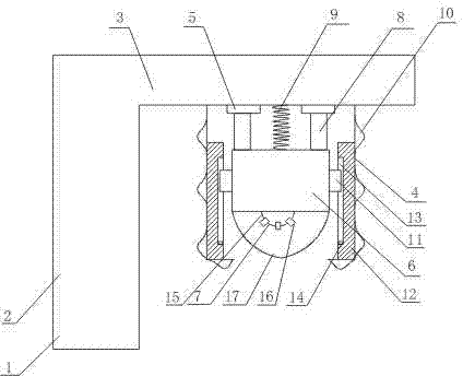
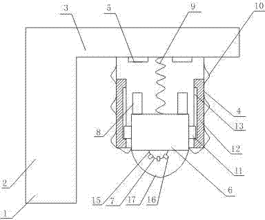
[0016] Such as figure 1 , figure 2 As shown, a safe and reliable community security system includes an L-shaped support 1, and the L-shaped support 1 is composed of a vertical rod 2 and a horizontal rod 3, wherein the vertical rod 2 is fixed on the ground, and the horizontal rod 3 is connected to the vertical The upper end of the rod 2; also includes a decorative shell 4 arranged vertically downward on the horizontal rod 3, the decorative shell 4 is a cavity structure with a lower opening; Section 6 and the imaging device 7 arranged on the lower surface of the connecting section 6, the width of the imaging device 7 is smaller than the diameter of the lower opening of the decorative shell 4; it also includes connecting rods 8 arranged on both sides of the upper surface of the connecting section 6 and made of iron, It also includes a compression spring 9 with one end connected to the top of the decorative shell 4 and the other end connected to the connecting section 6; an infr...

Embodiment 2

[0019] On the basis of Embodiment 1, this embodiment also includes sliders 11 respectively fixed on both sides of the connecting section 6 and slide rails 12 arranged on both sides of the inner wall of the decorative shell 4, and the side walls of the slide rails 12 are provided with slits 13 , the slider 11 slides into the slit 13 ; it also includes a trigger switch 14 arranged at the bottom of the slit 13 . The imaging device 7 includes a rotation control mechanism electrically connected to the trigger switch 14 and a hemispherical body 15 driven by the rotation control mechanism, and also includes a camera 16 uniformly arranged on the outer surface of the hemispherical body 15 around the center of the hemispherical body 15 .

[0020] In this embodiment, when the connecting section 6 moves downward until the slider 11 touches the trigger switch 14 at the bottom of the slit 13, the rotation control mechanism electrically connected to the trigger switch 14 will be activated to ...

Embodiment 3

[0022] On the basis of Embodiment 1 or Embodiment 2, this embodiment further includes a protective cover 17 detachably arranged on the lower surface of the connecting section 6 , and the camera device 7 is located in the protective cover 17 .

[0023] In this embodiment, the protective cover 17 protects the camera device 7 and prevents the camera device 7 from being damaged due to wind and sun.


PUM


Abstract

The invention records a safe and reliable community security system, which comprises an L-shaped support; the L-shaped support consists of a vertical bar and a horizon bar; the safe and reliable community security system also comprises a decorative shell, electromagnets, a connecting piece, a camera head, connecting rods, a compression spring and infrared probes, wherein the decorative shell is vertically arranged on the horizon bar downwards; the decorative shell is of a cavity structure of which the lower part forms an opening; the electromagnets are respectively and fixedly arranged at two sides of the top part of the decorative shell; the camera head is arranged on the lower surface of the connecting piece; the width of the camera head is less than the diameter of the opening of the lower part of the decorative shell; the connecting rods are respectively arranged at two sides of the upper surface of the connecting piece and are respectively made of iron; one end of the compression spring is connected with the top part of the decorative shell, and the other end of the compression spring is connected onto the connecting piece; the infrared probes are evenly arranged on the outer surface of the decorative shell. According to the safe and reliable community security system recorded by the invention, through the installation of the electromagnets and sliding rails, monitoring equipment is hidden in the decorative shell when no object enters a monitored region, and therefore the phenomenon that a thief takes measures to avoid the monitoring of the camera head after noticing the monitoring equipment is avoided, and the action of prevention and deterrence is exerted on the thief.

Description

technical field [0001] The invention relates to a monitoring device, in particular to a safe and reliable community security system. Background technique [0002] Existing cameras can rotate 360° left and right, and 90° up and down, and can basically monitor from all angles without dead angles. avoid. Furthermore, after the thieves realize that there is monitoring equipment at the crime site, they will generally take corresponding measures to avoid the monitoring of the camera. Let the thieves get away with it. Contents of the invention [0003] In order to solve the defects of existing monitoring equipment such as being easy to be found and having dead spots in monitoring, the present invention provides a safe and reliable community security system. [0004] Technical scheme of the present invention is as follows: [0005] A safe and reliable community security system, including an L-shaped bracket, the L-shaped bracket is composed of a vertical rod and a horizontal r...

Claims


Application Information

Patent Timeline
Patent Type & Authority Applications(China)
IPC IPC(8): F16M11/06F16M11/18
Inventor 彭小川
Owner MIANYANG HAOMAI ELECTRONICS SCI & TECH CO LTD
Why Eureka
Try Eureka