Image brightness correction method

A technology of image brightness and correction coefficient, applied in the field of image processing, can solve problems such as poor correction effect and slow running speed, achieve better and more detailed effects, improve running speed, and ensure the effect of image quality

Inactive Publication Date: 2015-07-15
TRULY OPTO ELECTRONICS
View PDF4 Cites 12 Cited by
  • Summary
  • Abstract
  • Description
  • Claims
  • Application Information

AI Technical Summary

Problems solved by technology

[0004] The purpose of the present invention is to provide a method for image brightness correction, aiming to solve the problems of slow running speed or poor correction effect of existing brightness correction methods

Method used


Image

  • Image brightness correction method
  • Image brightness correction method
  • Image brightness correction method

Examples


Embodiment 1

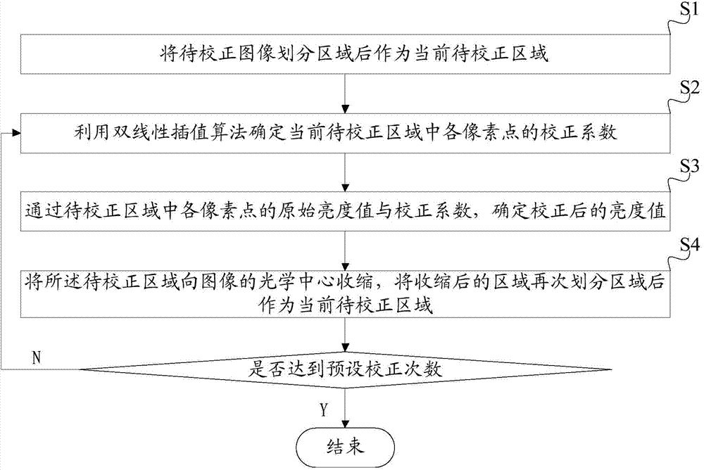
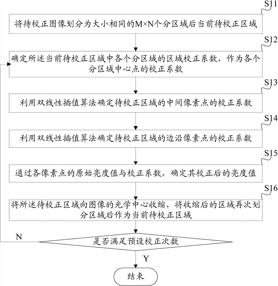
[0040] The flow chart of a specific embodiment of the image brightness correction method provided by the present invention is as follows figure 2 shown. In the above step S1, dividing the image to be corrected into regions as the current region to be corrected can be specifically as follows:

[0041] Step S11: Divide the image to be corrected into M×N sub-areas of the same size as the current area to be corrected, where M and N are both odd numbers, and the proportional relationship between M and N is proportional to the size of the image .

[0042] The above step S2 uses the bilinear interpolation algorithm to determine the correction coefficient of each pixel in the current area to be corrected. Specifically, the following steps can be taken:

[0043] Step S12: Determine the area correction coefficients of each sub-area in the current area to be corrected as the correction coefficient of the center point of each sub-area;

[0044] Specifically, the average brightness of ...

Embodiment 2

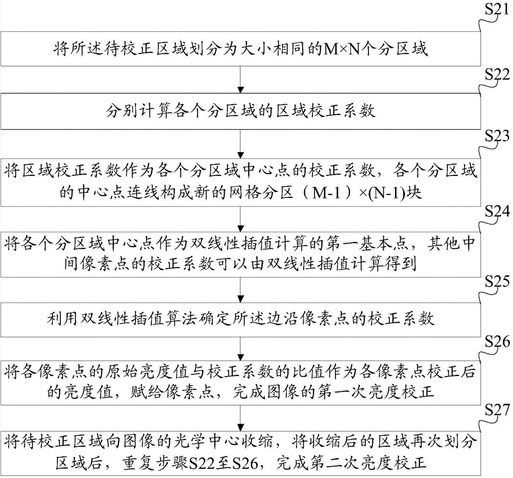
[0059] The flow chart of another specific embodiment of the image brightness correction method provided by the present invention is as follows image 3 As shown, compared with the previous embodiment, the preset number of corrections in this embodiment is set to 2, that is, two-level bilinear interpolation correction is performed. This example includes:

[0060] Step S21: Divide the area to be corrected into M×N sub-areas of the same size, where M and N are both odd numbers, and the proportional relationship between M and N is proportional to the size of the image;

[0061] Wherein, as a preferred implementation manner, the divided sub-areas may specifically be several small square areas of the same size as the first-level divided areas.

[0062] Step S22: Calculate the average brightness of the pixels in each sub-region, determine the maximum value of the average brightness, and use the ratio of the average brightness of each sub-region to the maximum value as the regional c...


PUM


Abstract

The invention discloses an image brightness correction method which comprises steps as follows: S1, taking a partitioned to-be-corrected image as a current to-be-corrected zone; S2, determining correction coefficients of all pixels in the current to-be-corrected zone with a bilinear interpolation algorithm; S3, determining brightness values of the pixels after correction according to original brightness values and the correction coefficients of the pixels in the current to-be-corrected zone; S4, contracting the to-be-corrected zone towards the optical center of the image, partitioning the contacted zone again, taking the partitioned zone as the current to-be-corrected zone, and returning to S2 until the preset correction times are reached. With the adoption of the image brightness correction method, the brightness correction running speed can be greatly increased, the method is more applicable to practical application of a production line, the correction result can be more detailed, and the quality of corrected images is guaranteed.

Description

technical field [0001] The invention relates to the technical field of image processing, in particular to a method for correcting image brightness. Background technique [0002] Due to the optical characteristics of the lens, the light intensity received by the edge area of ​​the sensor is smaller than that of the center area, and vignetting will appear in the image screen. When the camera module performs tests such as focusing and resolution, if the picture is too dark or has vignetting, it will seriously affect the test results. The impact of such factors on test items can be mitigated if brightness compensation is performed prior to testing. In addition, brightness correction is performed first when testing the module, which can also make problems such as mechanical vignetting, bright spots, and bright lines more obvious, so that it is more convenient to judge the defects of the module. [0003] Correcting the brightness of each pixel according to the cosine fourth powe...

Claims


Application Information

Patent Timeline
Patent Type & Authority Applications(China)
IPC IPC(8): G06T5/00
Inventor 张博张粦钢李建华
Owner TRULY OPTO ELECTRONICS
Why Eureka
Try Eureka