Method for calculating action time of three vectors of three-level inverter
A technology of vector action time and action time, applied to electrical components, output power conversion devices, irreversible DC power input conversion to AC power output, etc., can solve problems such as complex calculation process and error-prone
- Summary
- Abstract
- Description
- Claims
- Application Information
AI Technical Summary
Problems solved by technology
Method used
Image

Examples
Embodiment 1
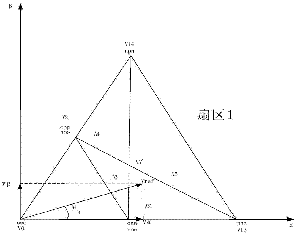
[0057] Embodiment 1, when the first voltage vector When it falls in the A1 small sector (a second sector) of the large sector (the first sector), the first voltage vector V in the A1 small sector ref The vector decomposition diagram after coordinate transformation, such as Figure 4 shown.
[0058] Coordinate transformation:
[0059] Method: Transform the coordinate system of the first voltage vector at this moment, specifically, the starting point of the first voltage vector is the origin, and the side (α-axis) of the initial sector extending from the starting point is taken as the horizontal axis, and a straight line (β-axis) perpendicular to the side is taken as the vertical axis to form an initial coordinate system. Connect the end point of the first voltage vector corresponding to the initial coordinate system to a vertex of the same second sector Taking the vertex as the origin and connecting the termination point to form a second voltage vector, and taking the ve...
Embodiment 2
[0085] Embodiment 2, when the first voltage vector When it falls in the small sector A2 of the large sector, the first voltage vector V in the small sector A2 red The vector decomposition diagram after coordinate transformation, such as Figure 5 shown.
[0086] Coordinate transformation: the method is the same as that in Embodiment 1, and will not be repeated here.
[0087] main, the first voltage vector Carry out coordinate transformation to get new coordinates: as the origin of coordinates, with as a coordinate axis, with The coordinate system composed of another coordinate axis is the reference coordinate system, and the second voltage vector at this moment is arrive connection
[0088] In the second voltage vector vertex, make two parallel lines, parallel to the coordinate axis and axes the new vector formed by the intersection of the two axes with is the second voltage vector Two decomposed vectors after coordinate transformation.
[0089] Thr...
Embodiment 3
[0110] Embodiment 3, when the first voltage vector When it falls in the small sector A3 of the large sector, the first voltage vector V in the small sector A3 ref The vector decomposition diagram after coordinate transformation, such as Image 6 shown.
[0111] Coordinate transformation: the method is the same as that in Embodiment 1, and will not be repeated here.
[0112] Carry out coordinate transformation on the first voltage vector to obtain new coordinates, with as the origin of coordinates, with as a coordinate axis, with The coordinate system composed of another coordinate axis is the reference coordinate system, and the second voltage vector at this moment is arrive connection
[0113] In the second voltage vector vertex, make two parallel lines parallel to the coordinate axis and axes the new vector formed by the intersection of the two axes with is the second voltage vector Two decomposed vectors after coordinate transformation.
[0114] ...
PUM
 Abstract
Description
Claims
Application Information
 - R&D
- Intellectual Property
- Life Sciences
- Materials
- Tech Scout
- Unparalleled Data Quality
- Higher Quality Content
- 60% Fewer Hallucinations
Browse by: Latest US Patents, China's latest patents, Technical Efficacy Thesaurus, Application Domain, Technology Topic, Popular Technical Reports.
© 2025 PatSnap. All rights reserved.Legal|Privacy policy|Modern Slavery Act Transparency Statement|Sitemap|About US| Contact US: help@patsnap.com