

Electric car and bi-directional inversion type motor controller
A motor controller, electric vehicle technology, applied in electric vehicles, control drive, electric traction, etc., can solve the problems of long charging time, limited use, high price, etc., and achieve the effect of increasing battery life and wide use
- Summary
- Abstract
- Description
- Claims
- Application Information
AI Technical Summary
Problems solved by technology
Method used
Image

Examples
Embodiment Construction
[0048] In order to make the technical problems, technical solutions and beneficial effects solved by the present invention clearer, the present invention will be further described in detail below in conjunction with the accompanying drawings and embodiments. It should be understood that the specific embodiments described here are only used to explain the present invention, not to limit the present invention.
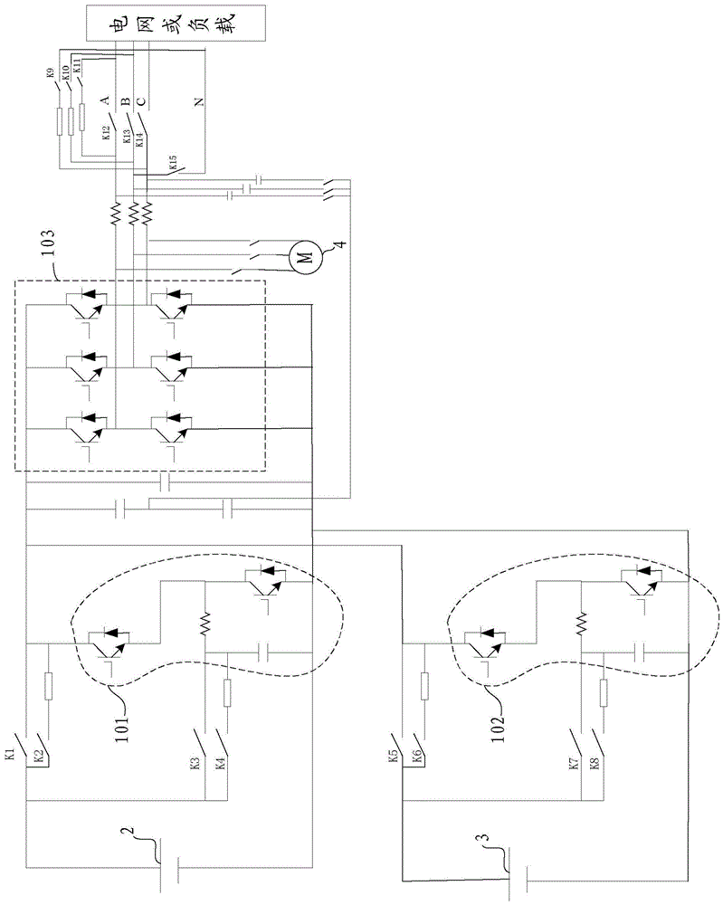
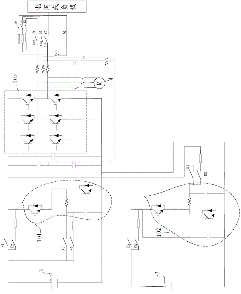
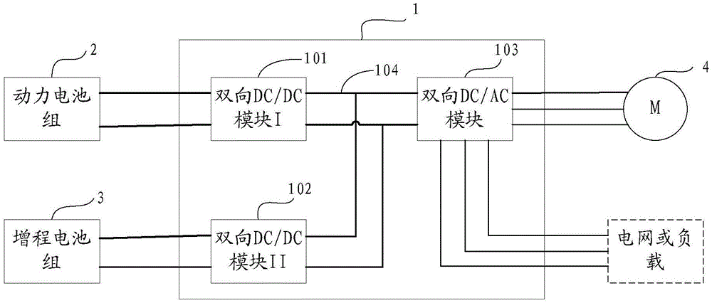
[0049] Please refer to figure 1 , is a schematic structural view of the first embodiment of the electric vehicle provided by the present invention. The electric vehicle includes: a motor controller 1 , a power battery pack 2 , a range-extending battery pack 3 and a motor 4 .
[0050] Wherein, the motor controller 1 may be a bidirectional inverter motor controller. The so-called bidirectional inverter means that the motor controller 1 can realize the mutual interaction between DC (Direct Current, direct current) and AC (Alternating Current, alternating current). convert...
PUM
 Abstract
Description
Claims
Application Information