Automatic conveying device

A conveying device and conveying belt technology, applied in the field of automated conveying devices

Inactive Publication Date: 2015-07-22
SHANGHAI CHANGYU COMM TECH CO LTD
View PDF0 Cites 0 Cited by
  • Summary
  • Abstract
  • Description
  • Claims
  • Application Information

AI Technical Summary

Problems solved by technology

[0003] However, the existing conveyor belts may be limited by the geographical location of the factory building, some will be set up in a slope shape, and some

Method used


Image

  • Automatic conveying device
  • Automatic conveying device
  • Automatic conveying device

Examples


Embodiment Construction

[0023] The following are specific embodiments of the present invention in conjunction with the accompanying drawings to further describe the technical solutions of the present invention, but the present invention is not limited to these embodiments.

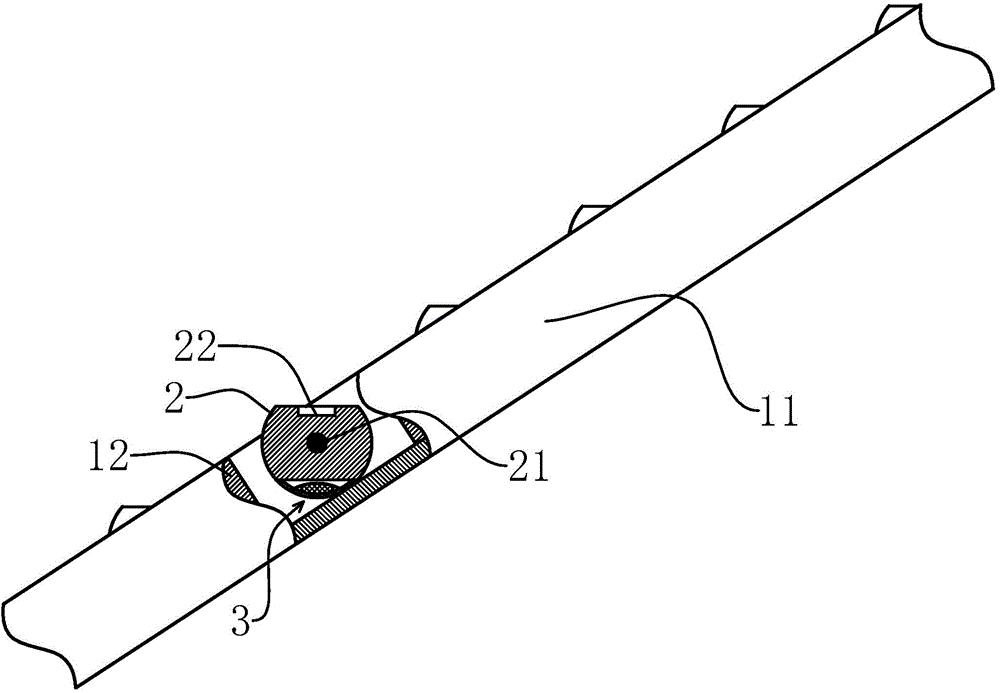
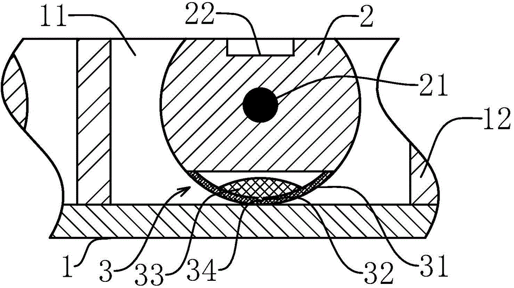
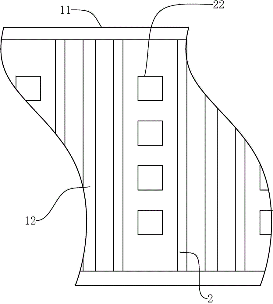
[0024] Such as Figure 1-3 As shown, an automated conveying device of the present invention includes a conveyor belt 1, and also includes two ribs 11, the two ribs 11 are arranged parallel to each other on the conveying surface of the conveyor belt 1, and the ribs 11 are along the conveyor belt 1 The conveying direction is set, and it also includes a carrier plate 2. The carrier plate 2 is arranged between the two ribs 11 through a rotating shaft 21, and the rotating shaft 21 is perpendicular to the rib 11, and the top of the carrier plate 2 has a loading slot 22, A counterweight device 3 is detachably connected to the bottom of the plate 2, and the direction of the slot of the loading slot 22 can be adjusted by adjusting the counte...


PUM


Abstract

The invention provides an automatic conveying device, and belongs to the field of automatic electromechanical technologies. The purpose of conveying an existing product at a fixed angle on a conveying belt in the prior art is solved. The automatic conveying device comprises a conveying belt and two stopping edges arranged on the conveying surface of the conveying belt in parallel, the stopping edges are arranged in the conveying direction of the conveying belt, and the automatic conveying device further comprises a carrying plate arranged between the two stopping edges through a rotating shaft. The rotating shaft is perpendicular to the stopping edges, carrying grooves are formed in the top of the carrying plate, a counterweight device is detachably connected to the bottom of the carrying plate, and the direction of openings of the carrying grooves can be adjusted through adjusting the counterweight device. Products are placed into the carrying grooves which play a role in positioning; because the counterweight device is connected to the bottom of the carrying plate, the counterweight device and the rotating shaft are matched to make the carrying plate form a fixed angle, and the direction of the openings of the carrying grooves is quite stable. In this way, the conveying device is quite suitable for products needing to be conveyed at fixed angles.

Description

Technical field [0001] The invention belongs to the field of automatic electromechanical technology and relates to an automatic conveying device. Background technique [0002] In the middle of the 17th century, the United States began to use aerial ropeways to transport bulk materials; in the middle of the 19th century, conveyor belt conveyors of various modern structures appeared one after another. In 1868, belt conveyors appeared in England; in 1887, screw conveyors appeared in the United States; in 1905, steel belt conveyors appeared in Switzerland; in 1906, inertial conveyors appeared in Britain and Germany. Since then, the conveyor belt conveyor has been continuously improved by the technological advancement of machinery manufacturing, electrical machinery, chemical and metallurgical industries, and has gradually developed from completing the transmission within the workshop to completing the material handling within the enterprise, between enterprises and even between citie...

Claims


Application Information

Patent Timeline
IPC IPC(8): B65G15/58
CPCB65G15/58B65G2812/02217
Inventor 陈树丽
Owner SHANGHAI CHANGYU COMM TECH CO LTD
Why Eureka
Try Eureka