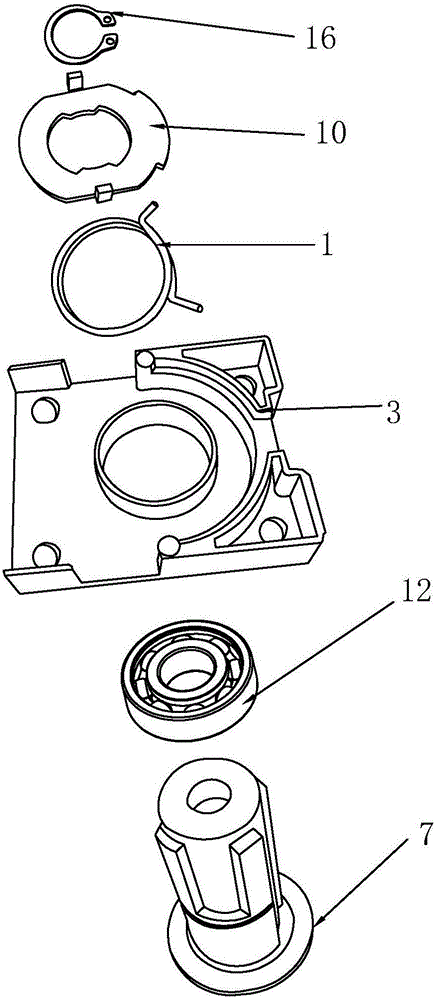
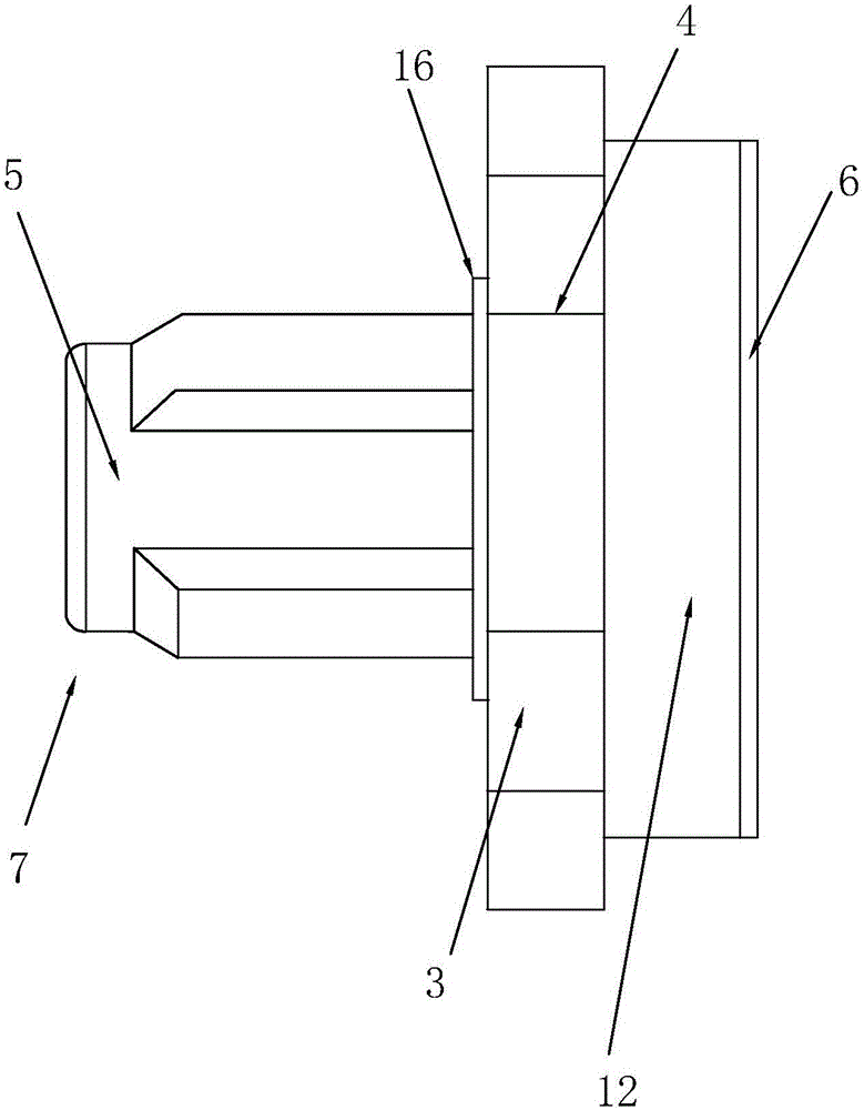
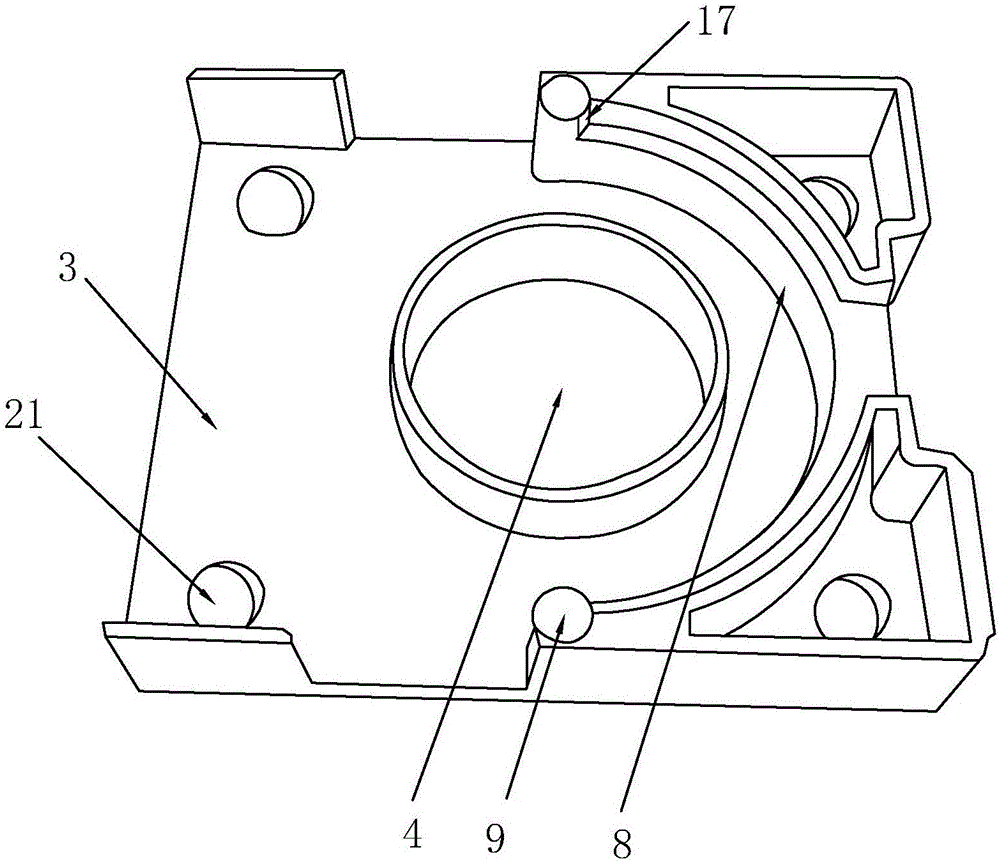
However, with reference to the specification of the patent image 3 And as shown in the specific embodiment [0021], the bearing is interposed between the fixed plate and the handle head, and the bearing ring is arranged on the periphery of the second installation end, and the stopper is against the Bearings are used to ensure that the bearings are firmly installed between the fixing plate and the handle, which will cause linear physical wear between the stopper and the bearing during use, and friction will occur at the stopper After being damaged, the relative movement of the bearing on the fixed plate is caused, which is not only inconvenient to open the door, but also affects its service life
[0003] And the Chinese utility model that application number is 201320482674.0 discloses a kind of novel door lock handle panel structure, comprises panel and handle, and the rotating shaft of described handle is provided with bayonet, and described panel is provided with handle through hole, bearing groove, Positioning columns, positioning piles and panel fixing holes; a bearing is installed in the bearing groove, the inner ring of the bearing is 0.5-2mm higher than the outer ring and the upper end surface of the bearing groove, and a return spring is set on the outside of the bearing groove. The positioning end of the return force spring is stuck on the positioning column in a cross shape, and the return spring is provided with an actuating piece, and the actuating piece is provided with a shift fork, and the fork is inserted between the two positioning ends of the return force spring. A snap ring and a nut are arranged on the starting piece, the inner side of the snap ring is provided with snap teeth matching the bayonet on the handle shaft, and the outer side of the snap ring is provided with an upturning piece that can be turned up to hold the nut; refer to the patent Instructions attached figure 1 And as shown in the specific implementation method [0014], a bearing is installed in the bearing groove, and the inner ring of the bearing is higher than the outer ring and the upper end surface of the bearing groove by 0.5-2mm, but although the return spring and the bearing are arranged at intervals, in this During the use of the patented product, the return spring in the working state will stretch or shrink, and it is easy to alternately conflict with the bearing and separate during work, causing mutual wear between the two, which is not conducive to the extension of the service life
[0004] In addition, the application number 201320482674.0 or 201320730652.1 both disclose a handle lock. For example, the Chinese utility model with the application number 201320730652.1 discloses a handle lock bearing linkage mechanism, including a bearing base plate, a bearing panel, a bearing, a return spring and a starting The bearing base plate and the bearing panel are provided with handle penetration holes, the bearing base plate is provided with spring positioning piles and spring travel positioning openings, and the bearing panel is provided with positioning
pile holes that match the spring positioning piles. The bearing is composed of an outer ring and an inner ring. The inner ring is provided with an upper convex edge and a lower convex edge. The upper convex edge is provided with a bayonet. hook; the inner ring of the bearing is inserted into the handle penetration hole of the bearing bottom plate, the return spring is fixed on the starting piece and is set outside the bearing together, so that the bayonet piece of the starting piece is snapped into the bayonet, and the bearing panel is locked On the bearing bottom plate; refer to the specification attached to the patent Image 6 And shown in the specific embodiment [0025], the spring positioning hook is arranged between the two ends of the return force spring, and the return force spring of this setting is a hanging spring, and the tension force is not enough, and in the process of forward and reverse rotation of the spring positioning hook, The elastic deformation of the return spring is relatively large, and its use frequency is about 170,000 times, which is far from meeting the current use requirements

