Positioning structure of antenna support and bogie

An antenna support and positioning structure technology, applied in bogies, antenna supports/installation devices, antennas suitable for movable objects, etc., can solve the problem of increased dynamic load of the antenna support, affecting driving safety, and single-head bolts 4 broken and other problems, to achieve the effect of improving the axial force state, increasing the length, and increasing the amount of elastic deformation.

Pending Publication Date: 2020-01-31
CRRC NANJING PUZHEN CO LTD
View PDF0 Cites 2 Cited by
  • Summary
  • Abstract
  • Description
  • Claims
  • Application Information

AI Technical Summary

Problems solved by technology

[0004] However, if Figure 4 , when the vehicle is running, the antenna bracket still has a tendency to rotate around the positioning pin 6, and a circumferential tangential shear force with the positioning pin 6 as the center acts on the stud bolt 4, especially when the line condition is poor and the bogie vibration increases When it is large, the dynamic load of the antenna bracket increases sharply, and the single-head bolt 4 is prone to fracture due to fatigue, which affects driving safety

Method used


Image

  • Positioning structure of antenna support and bogie
  • Positioning structure of antenna support and bogie
  • Positioning structure of antenna support and bogie

Examples


Embodiment Construction

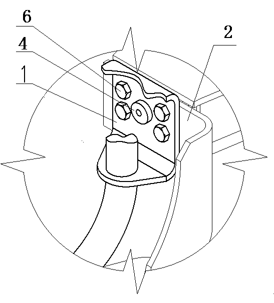
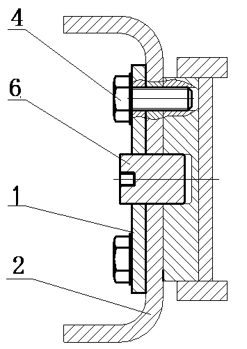
[0023] Such as Figure 5 with Image 6 As shown, the present invention proposes a positioning structure for the antenna support and the bogie, the bogie positioning plate 1 is arranged on the bogie, the antenna support is provided with the antenna support positioning plate 2; the bogie positioning plate 1 and the The antenna bracket positioning plate 2 is arranged in adhering manner to form a positioning installation pair. Four positioning through holes are arranged on the positioning installation pair. The positioning through holes are symmetrically arranged in pairs with respect to the same central point.

[0024] The positioning structure also includes two sets of bolt fasteners for fastening the positioning installation pair; each set of bolt fasteners includes two single-headed bolts 4 and a threaded hole base 5; the threaded hole base 5 is provided with There are two threaded holes 501 ; the two threaded holes 501 correspond to the two single-head bolts 4 one by one. ...


PUM


Abstract

The invention provides a positioning structure of an antenna support and a bogie. A bogie positioning plate is arranged on the bogie, and an antenna support positioning plate is arranged on the antenna support; the bogie positioning plate and the antenna support are fitted together to form a positioning mounting pair; the positioning structure further comprises a plurality of bolt fasteners used for fastening the positioning mounting pair; the positioning mounting pair is provided with a plurality of positioning through holes; one screw rod of each bolt fastener penetrates through one positioning through hole; positioning sleeves with rigid materials are arranged between the screw rods and the positioning through holes; the outer walls of the positioning sleeves are in interference fit with the inner walls of the positioning through holes; and the inner walls of the positioning sleeves are in clearance fit with the screw rods. According to the positioning structure, the positioning sleeves are arranged between the screw rods and the positioning through holes, positioning pins are matched, positioning of the antenna support and the bogie on the connecting plane is achieved, the positioning sleeves and the positioning pins are subjected to shearing force under various working conditions, the situation that the single-end bolt is subjected to transverse shearing force under various working conditions is avoided, and the phenomenon that the single-end bolt is broken due to fatigue is avoided.

Description

technical field [0001] The invention belongs to the field of rail vehicle equipment, and in particular relates to a positioning structure for an antenna bracket and a bogie. Background technique [0002] Such as figure 1 , An antenna bracket is installed on the bogie, and the antenna bracket is used as the carrier of the subway or EMU signal equipment, and its reliability is directly related to the safety of the entire vehicle. [0003] The positioning structure of the existing antenna support and bogie is shown in Figure 2 and image 3 The antenna support positioning plate 1 and the bogie positioning plate 2 are positioned through the positioning pin 6, and the single head bolt 4 is screwed into the threaded hole of the bogie positioning plate 2, and the antenna support is tightly connected with the bogie. When the vehicle is running, the antenna bracket produces a linear displacement trend on the plane of the positioning plate of the bogie, the positioning pin 6 bears th...

Claims


Application Information

Patent Timeline
Patent Type & Authority Applications(China)
IPC IPC(8): B61F5/50H01Q1/12H01Q1/32
CPCB61F5/50H01Q1/12H01Q1/32
Inventor 徐力金伟冯遵委谢莹莹贾小平周勇张龙波
Owner CRRC NANJING PUZHEN CO LTD
Why Eureka
Try Eureka