Telescopic compensation connector for vacuum traffic pipeline

A pipeline and transportation technology, which is applied to expansion compensation devices for pipelines, pipes/pipe joints/pipes, pipe components, etc. It can solve the high cost of corrugated expansion joints, the inability to compensate for packing, and the inapplicability of displacement compensation for vacuum transportation pipelines, etc. question

Pending Publication Date: 2018-12-21
SOUTHWEST JIAOTONG UNIV
View PDF7 Cites 2 Cited by
  • Summary
  • Abstract
  • Description
  • Claims
  • Application Information

AI Technical Summary

Problems solved by technology

The sleeve type compensator is composed of three parts: the casing, the cannula and the sealing packing. It compensates the thermal deformation of the pipeline by the relative movement of the cannula and the casing. The disadvantage is that there is not much packing itself. Back and forth expansion and contraction, the sealing packing is easy to wear, and the packing itself cannot compensate after wear, so the packing needs to be replaced frequently, resulting in easy leakage of the sleeve compensator; when the pipe has a slight radial and angular displacement, it is easy to cause the sleeve to be stuck The phenomenon
The compensation amount of the bellows expansion joint is relatively small relative to its own axial dimension, and the bellows expansion joint with a long axial dimension can only compensate a relatively small displacement, which will make the distance between the two ends of the pipe connected too large, and its structure is The flexible corrugated structure, on which it is inconvenient to lay tracks, leads to the excessive distance between the tracks inside the straight ends of two adjacent pipes, and vehicles cannot easily cross over
Moreover, the cost of corrugated expansion joints is relatively high
Therefore, the existing compensation methods are not suitable for displacement compensation of vacuum traffic pipelines

Method used


Image

  • Telescopic compensation connector for vacuum traffic pipeline

Examples


Embodiment 1

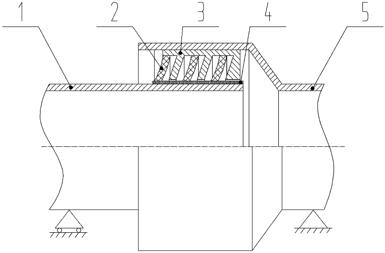
[0016] Embodiment 1: attached figure 1 represents this example

[0017] The straight end 1 of the pipe and the socket end 5 of the pipe are made of steel, and can also be ordinary carbon steel, stainless steel, weathering steel or other materials capable of sealing gas. One of the two butted pipe ends is fixed, and the other is movable in the axial direction. A sealing layer 4 on the outer surface of the pipe is laid along the outer diameter surface of the straight end 1 of the pipe. The sealing layer 4 on the outer surface of the pipe needs to have certain wear resistance, elasticity and self-lubricating properties. The sealing layer 4 on the outer surface of the tube can be made of materials such as expanded graphite or carbon fiber reinforced polytetrafluoroethylene. Among them, expanded graphite has excellent properties such as good compressibility, resilience, self-adhesiveness, low density, etc., and can be used for a long time under high temperature and highly corrosi...


PUM


Abstract

The invention provides a telescopic compensation connector for a vacuum traffic pipeline, and relates to the technical field of vacuum pipeline compensation of vacuum rail traffic. The telescopic compensation connector comprises a pipeline straight-opening end and a pipeline bell end for expanding of adjacent pipelines; a surface sealing layer is arranged on the outer wall of a connecting part ofthe pipeline straight-opening end, and a hard supporting plate ring with the section being in a comb tooth shape is arranged on the pipeline inner wall of a connecting part of the pipeline bell end; an annular soft seal blade plate is arranged in a comb-shaped gap of the hard supporting plate ring; the outer diameter of the annular soft seal blade plate and the inner diameter of the hard supporting plate ring are fixed; the end face of the inner diameter of the annular soft seal blade plate makes contact with the pipe end surface sealing layer, and the tooth-shaped annular inner surface of thehard supporting plate ring is in clearance fit with the surface sealing layer of the pipeline straight-opening end; the comb tooth gap of the hard supporting plate ring is greater than the thicknessof the annular soft seal blade plate; and the end face of the inner diameter of the annular soft seal blade plate makes contact with the surface sealing layer. The telescopic compensation connector can be applied to construction of the vacuum traffic pipeline.

Description

technical field [0001] The invention relates to the field of vacuum pipeline compensation devices for vacuum rail transit, in particular to the expansion and contraction compensation interface of vacuum pipelines. Background technique [0002] In the post-high-speed rail era, on the one hand, it is more and more difficult to increase the speed of rail trains using wheel-rail technology; increasingly uneconomical. In this case, the application of vacuum pipeline technology to allow rail vehicles to run in pipelines in a vacuum-like environment to achieve multiple purposes such as increasing speed, reducing resistance, energy saving and environmental protection has become a new scientific research frontier in the field of rail transit technology. Southwest Jiaotong University in my country and Hyperloop One in the United States have both built vacuum tube test lines, and a research upsurge in vacuum tube trains has been set off at home and abroad. [0003] In practical appli...

Claims


Application Information

Patent Timeline
Patent Type & Authority Applications(China)
IPC IPC(8): F16L51/00F16L27/12F16J15/447
CPCF16J15/4476F16L27/12F16L51/00
Inventor 张卫华叶联龙
Owner SOUTHWEST JIAOTONG UNIV
Why Eureka
Try Eureka