Counterflow Grain Drying Equipment

A grain drying, counter-current technology, applied in the field of counter-current grain drying equipment, can solve the problems of short heating time, low drying efficiency, high exhaust temperature, etc.

Active Publication Date: 2017-10-03
SHANDONG REALIFE DRYING MACHINERY TECH CO LTD
View PDF5 Cites 0 Cited by
  • Summary
  • Abstract
  • Description
  • Claims
  • Application Information

AI Technical Summary

Problems solved by technology

With this kind of dryer, the hot air flows horizontally in the drying bin, the grains fall fast and the heating time is short, the grains are only heated briefly in the drying bin, and no longer heated in the recovery bin, and the drying efficiency of a single cycle is low , high exhaust temperature, low thermal efficiency

Method used


Image

  • Counterflow Grain Drying Equipment
  • Counterflow Grain Drying Equipment
  • Counterflow Grain Drying Equipment

Examples


Embodiment Construction

[0015] The present invention will be further described below in conjunction with the accompanying drawings and specific embodiments.

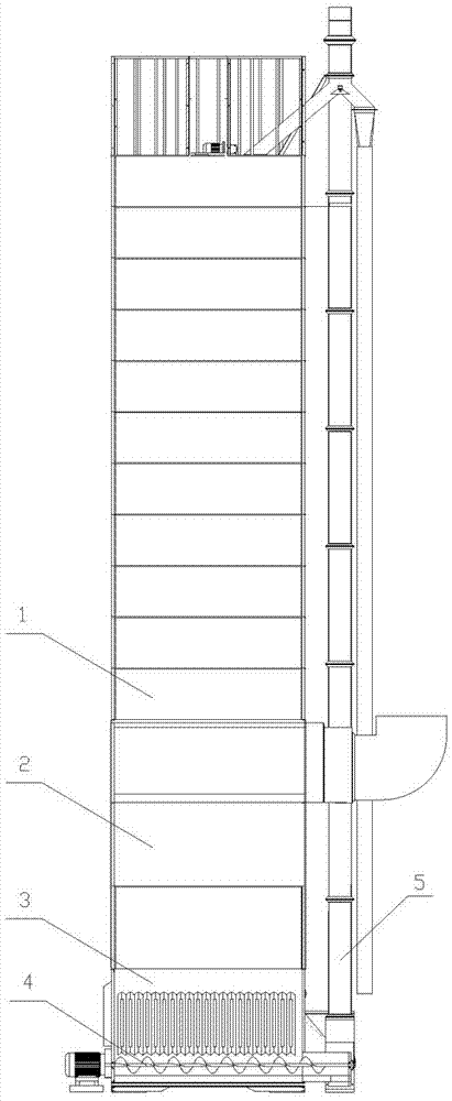
[0016] like figure 1 As shown, the counter-current grain drying equipment of the present invention includes a barn 1, a drying bin 2 located below the barn 1, and a recovery bin 3 located below the drying bin 2, and the recovery bin 3 is provided with an auger Conveyor 4, the output end of the auger conveyor 4 is connected to the input end of the material lifter 5, and the output end of the material lifter 5 is connected to the feed port at the upper end of the barn 1. The grain in the barn 1 passes through the drying bin 2 and falls into the recovery bin 3 under the action of gravity, and is heated and dried during the falling process, and the grain in the recovery bin 3 is sent back by the auger conveyor 4 and the material lifter 5 Go to Barn 1 for the next drying cycle.

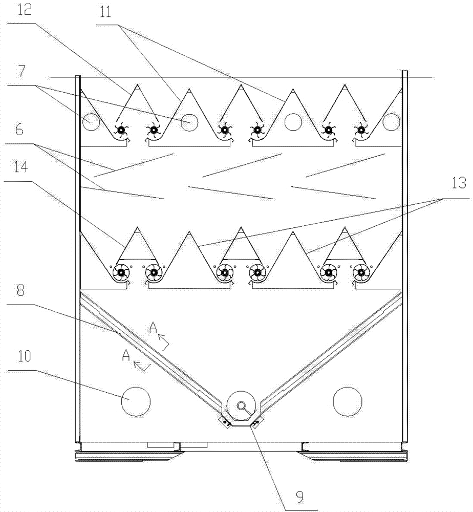
[0017] like figure 2 As shown, the upper end of the drying bin 2 i...


PUM


Abstract

The invention relates to a grain drying equipment used for drying grain, in particular to a countercurrent grain drying equipment. It includes a barn, a drying bin located under the barn, and a recovery bin located under the drying bin. An auger conveyor is arranged in the recovery bin, and the output end of the auger conveyor is connected to the input end of the material lifter , the output end of the material lifter is connected to the feed port at the upper end of the barn, and several inclined deflectors are arranged in the drying bin; the upper end of the drying bin is provided with exhaust holes; the recovery bin is fixedly installed There is an obliquely arranged material guide and ventilation plate, and an air inlet is arranged on the side wall of the recovery bin below the material guide and ventilation plate. When the countercurrent grain drying equipment works, the drying air flow flows from bottom to top, which prolongs the heating path of the grain and reduces the speed of the grain falling. The drying efficiency is high, the drying speed is fast, and the thermal efficiency is high, which is beneficial to reduce energy consumption, Energy saving.

Description

technical field [0001] The invention relates to a grain drying equipment used for drying grain, in particular to a countercurrent grain drying equipment. Background technique [0002] The barn of the existing circulating grain dryer is set above the drying bin, and the recovery bin is set under the drying bin. The hot air enters from the air inlet on one side of the drying bin and is discharged from the air outlet on the other side. The grains are heated and dried by hot air during the falling process, and the grains that fall into the recovery bin are transported to the barn through the lifting device, and the drying cycle is repeated in this way. With this kind of dryer, the hot air flows horizontally in the drying bin, the grains fall fast and the heating time is short, the grains are only heated briefly in the drying bin, and no longer heated in the recovery bin, and the drying efficiency of a single cycle is low , the exhaust outlet temperature is high, and the thermal...

Claims


Application Information

Patent Timeline
Patent Type & Authority Patents(China)
IPC IPC(8): F26B17/12F26B9/06A23B9/08F26B21/00F26B25/00
Inventor 韩振涛管耀文徐明亮魏同同
Owner SHANDONG REALIFE DRYING MACHINERY TECH CO LTD
Why Eureka
Try Eureka