
A dust jacket iron positioning device

A technology of positioning device and dust cover, which is applied in the direction of positioning device, feeding device, storage device, etc., and can solve the problems that iron parts are easy to run away from the original position and products are scrapped.

Active Publication Date: 2017-07-07
ZHEJIANG HONGLEE AUTO PARTS
View PDF6 Cites 0 Cited by
  • Summary
  • Abstract
  • Description
  • Claims
  • Application Information

AI Technical Summary

Problems solved by technology

[0003] The invention provides a positioning device for iron parts of the dust jacket, which aims to solve the problem in the prior art that the iron parts are easy to run away from the original position and cause the product to be scrapped

Method used


Image

  • A dust jacket iron positioning device
  • A dust jacket iron positioning device
  • A dust jacket iron positioning device

Examples


Embodiment 1

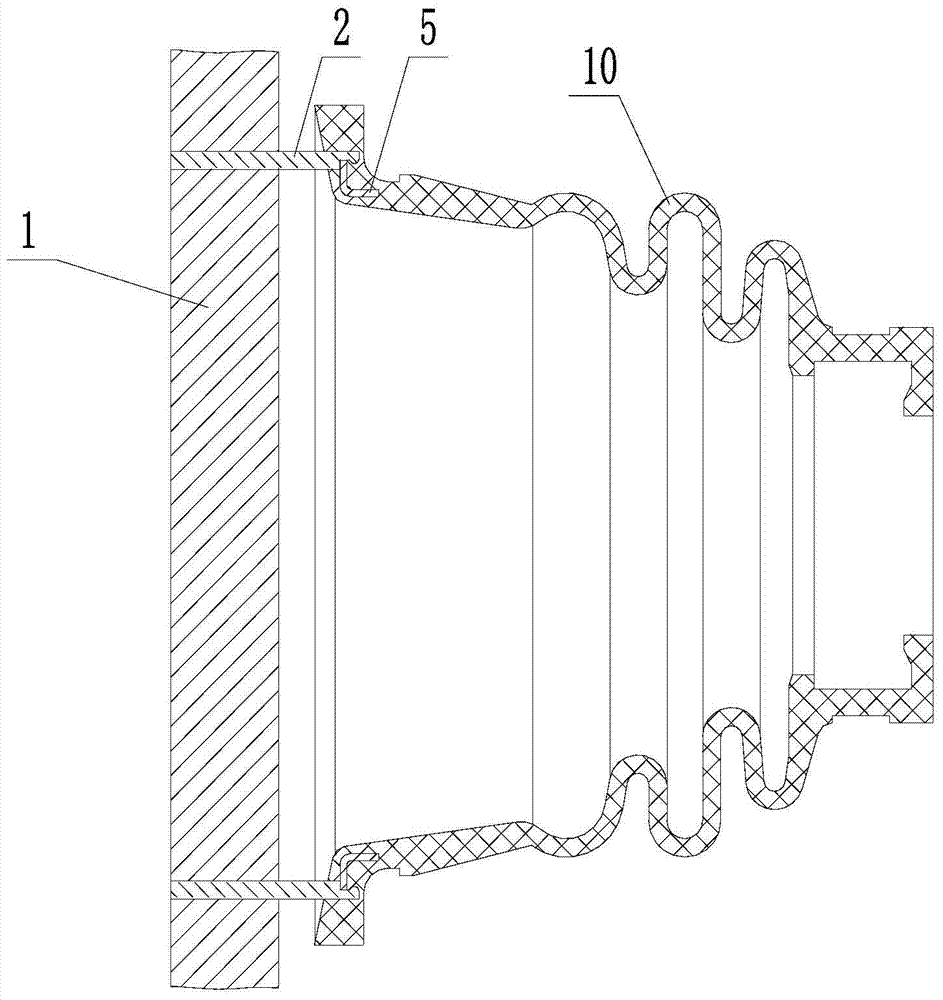
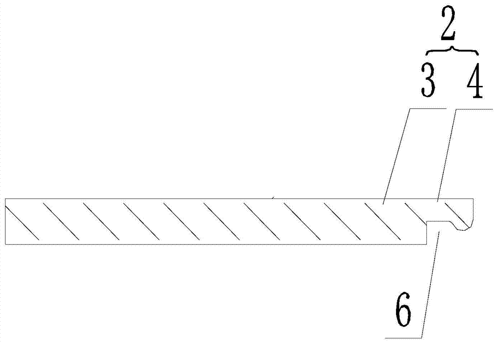
[0018] refer to figure 1 , figure 2 and image 3 , a dust-proof jacket iron parts positioning device, the dust-proof jacket iron parts 5 are composed of a round tube 51 and a convex eaves 52 surrounding one end of the outer wall of the round tube 51, including a vulcanization mold 1, four fixedly connected on the vulcanization mold 1 And the elastic hooks 2 evenly distributed on the same circumference, each elastic hook 2 is composed of a support rod 3 fixedly connected to the vulcanization mold 1, and an elastic pull hook 4 arranged on the support rod 3. A slot 6 for clamping the protruding eaves 52 is provided. The drag hook 4 is integrally arranged with the pole 3 .

[0019] The elastic hook 2 is made of spring steel. The bottom surface of the slot 6 is an arc-shaped surface matched with the protruding eaves 52 . Dustproof cover iron part 5 is set in the dustproof cover 10.

[0020] During installation, the four elastic hooks 2 are bent, and the dust-proof jacket iro...

Embodiment 2

[0022] refer to Figure 4 and Figure 5 , the difference from the first embodiment is that the pull hook 4 is detachably arranged on the pole 3 . The drag hook 4 is cylindrical, and the side wall of the drag hook 4 is provided with a slider 9; the inside of the pole 3 is provided with a blind hole 7 matched with the drag hook 4, and the inner wall of the blind hole 7 is provided with a slider 9 The matching chute 8, the chute 8 is composed of a straight groove 81 parallel to the axis of the blind hole 7 and having an outer end for the slider 9 to enter, and an arc-shaped groove 82 communicating with the straight groove 81 and used to lock the slider 9 constitute. The outer end of the straight groove 81 communicates with the outside, and the arc groove 82 is arranged in the circumferential direction of the blind hole 7;

[0023] The slider 9 on the side wall of the hook 4 reaches the bottom of the blind hole 7 along the straight groove 81, and the hook 4 is inserted into the...


PUM


Abstract

The invention provides a dustproof cover iron positioning device, and aims to solve the problem of product waste caused by easy deviation of an iron from an original position in the prior art. In the dustproof cover iron positioning device, a dustproof cover iron consists of a round tube, and a flange surrounding one end of the outer side wall of the round tube; the dustproof cover iron positioning device comprises a vulcanization mold, and at least three elastic hooks fixedly connected to the vulcanization mold and uniformly distributed on one periphery; each elastic hook consists of a support rod fixedly connected to the vulcanization mold, and a pull hook arranged on the support rod and having elasticity; and clamping grooves for clamping the flange are formed in the pull hooks. The dustproof cover iron positioning device clamps the dustproof cover iron among multiple elastic hooks through bending and resetting the elastic hooks, on the one hand, the iron is not liable to be deviated from the original position; and on the other hand, the problem of frequent maintenance and replacement caused by frangibility of a magnet under high temperature dose no exist.

Description

technical field [0001] The invention relates to the processing field of dustproof jackets, in particular to a positioning device for iron parts of dustproof jackets. Background technique [0002] At present, the suspension positioning of the iron parts of the dust jacket still adopts several simple cylindrical structures or magnet positioning on the market. Ordinary cylindrical positioning is adopted, and the iron parts are easy to run away from the original position, causing the product to be scrapped, resulting in huge economic losses. In order to solve the above problems, many enterprises use magnets for positioning. Although the problem of iron parts displacement is solved, high temperature magnets are fragile, which causes great inconvenience to mold making and maintenance. Contents of the invention [0003] The invention provides a positioning device for an iron part of a dust jacket, which aims to solve the problem in the prior art that the iron part is easy to run...

Claims


Application Information

Patent Timeline
Patent Type & Authority Patents(China)
IPC IPC(8): B21D43/00
CPCB21D43/003
Inventor 徐松宝袁建平梅军陈杰
Owner ZHEJIANG HONGLEE AUTO PARTS
Learn More