
Tool box convenient to use

A tool box and convenient technology, applied in the field of tool boxes, can solve the problems of single function, affecting the illumination range of lighting fixtures, inconvenient operation, etc., and achieve the effect of convenient use

Inactive Publication Date: 2015-08-05
NINGBO WEIJIA ELECTRONICS TECH
View PDF12 Cites 2 Cited by
  • Summary
  • Abstract
  • Description
  • Claims
  • Application Information

AI Technical Summary

Problems solved by technology

In each of the above-mentioned patents, lighting fixtures are arranged on the toolbox (or toolbox) to facilitate finding the tools in the toolbox in a dark environment, but the lighting fixtures in the above-mentioned patents are all arranged inside the toolbox, that is, the above-mentioned The lighting fixtures in the patent are mainly used for the lighting of tools in the box. If you want to use the lighting fixtures in the box to illuminate the working environment, you need to keep the lid of the tool box open for a long time. Wet, high-dust working environment) will have an impact on the tools in the tool box, especially those precision tools. At the same time, when the surrounding working environment is illuminated in this way, the box cover and the box body will block part of the lighting fixtures in the box Lighting rays, thus affecting the light range of lighting fixtures
[0004] It can be seen that although the tool boxes in the above-mentioned patents are convenient to a certain extent to find the tools in the box in dark places, the function of this kind of tool box is still relatively simple, and the tools in the tool box can be used in dark places. When performing operations, additional lighting tools are still needed to assist, and the operation is still inconvenient

Method used


Image

  • Tool box convenient to use
  • Tool box convenient to use
  • Tool box convenient to use

Examples


Embodiment Construction

[0019] The present invention will be further described in detail below in conjunction with the accompanying drawings and embodiments.

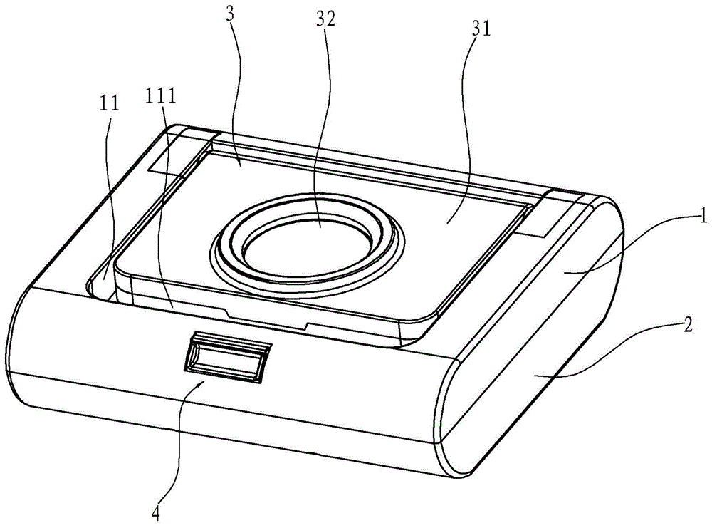
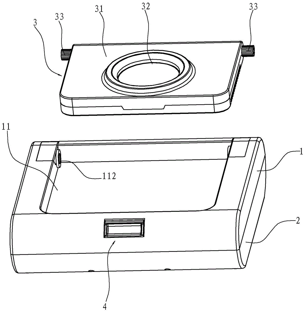
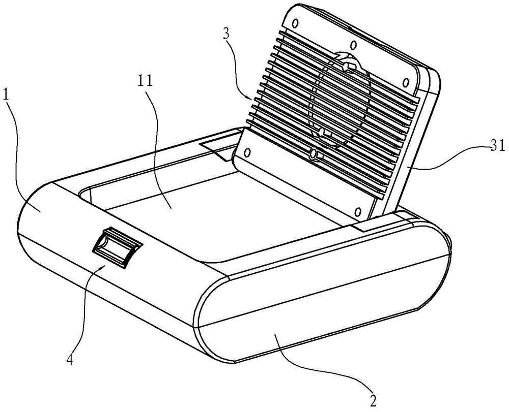
[0020] Such as Figure 1~4 As shown, a convenient tool box includes a box body 2 and a box cover 1 , and the outer top surface of the box cover 1 is depressed downward to form an accommodating groove 11 . The accommodating groove 11 is provided with a lighting fixture 3, and the lighting fixture 3 includes a lamp cap 31 and a luminous body 32 arranged on the lamp cap 31, wherein the lamp cap 31 is accommodated in the accommodating groove 11 and is in contact with the inner wall of the accommodating groove 11. It is hinged and can rotate relative to the accommodating groove 11 . When the lamp cap 31 is parallel to the bottom surface of the accommodating groove 11 , the top surface of the lamp cap 31 is flush with the box cover 1 . The setting of the accommodating groove 11 not only makes the connection between the lamp cap 31 and the box cover...


PUM


Abstract

The invention relates to a tool box convenient to use. The tool box comprises a box body and a box cover. The tool box is characterized in that the outer top surface of the box cover is provided with a lighting lamp, the lighting lamp comprises a lamp cap and a luminous body arranged on the lamp cap, and one end of the lamp cap is hinged to the box cover. The lighting lamp is arranged on the outer top surface of the box cover of the tool box, so that besides being used for finding tools in the box in the dark environment, the lighting lamp can also provide effective lighting for the operation environment; and due to the fact that the lighting lamp is arranged on the outer top surface of the box cover, the irradiation range of the lighting lamp is large. When the lighting lamp provides lighting for the operation environment, the box cover can be in a closed state, and accordingly the influence on the tools in the box caused by the operation environment can be avoided. On the other hand, one end of the lamp cap is hinged to the outer top surface of the box cover, so that the position of the lamp cap can be adjusted as required, the irradiation direction of the luminous body is adjusted, and the tool box is convenient to use.

Description

technical field [0001] The invention relates to a tool box, in particular to a convenient tool box with lighting function. Background technique [0002] The production, assembly, repair and maintenance of various equipment are inseparable from tools. Tools are not only used in factories, but also appear in the daily life of middle-aged and middle-aged families. In order to facilitate finding, carrying and using these tools, tool boxes came into being. At present, tool boxes on the market can be divided into two categories: one is metal tool boxes, which have the advantages of being stronger and more durable, but poor portability and bulkiness; the other is plastic tool boxes, which are Strong portability, light weight, but poor wear resistance. [0003] In addition, when the existing tool box is used in a dark place, other lighting tools are needed to find the tools in the box. Such a tool box is very inconvenient when used in the field of operation. For this reason people...

Claims


Application Information

Patent Timeline
Patent Type & Authority Applications(China)
IPC IPC(8): B25H3/02F21V33/00
CPCB25H3/022F21V33/0084
Inventor 马建烽
Owner NINGBO WEIJIA ELECTRONICS TECH
Learn More