Electro-thermal irradiation drying device

A drying device and electric heating technology, applied in the direction of heating device, drying, drying machine, etc., can solve the problems of poor material fixing effect, easy to be blown away, low drying efficiency, etc., to achieve drying and irradiation The effect of uniformity and expansion of the irradiation area

Pending Publication Date: 2017-08-04
浙江聚业科技有限公司
View PDF4 Cites 7 Cited by
  • Summary
  • Abstract
  • Description
  • Claims
  • Application Information

AI Technical Summary

Problems solved by technology

[0005] The present invention overcomes that in life or industrial production, materials often contain some water, and these waters need to be removed. The drying efficiency of the current drying device is low, the drying is uneven, and the fixing effect on the materials is not good. The shortcoming of being easily blown away during the drying process, the technical problem to be solved by the present invention is to provide an electric heating irradiation drying device

Method used


Image

  • Electro-thermal irradiation drying device
  • Electro-thermal irradiation drying device
  • Electro-thermal irradiation drying device

Examples


Embodiment 1

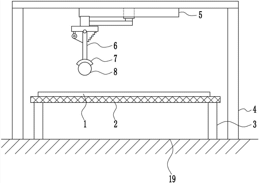
[0034] An electric heating irradiation drying device, such as Figure 1-5 As shown, it includes placing a grid plate 2, a first pole 3, a support 4, a rotating device 5, a swing device 6, a lampshade 7 and a warm light 8, and the ground 19 is provided with a first pole 3 and a support 4, and The first pole 3 is located inside the support 4, the top of the first pole 3 is provided with a grid plate 2, the top of the support 4 is provided with a rotating device 5, the bottom of the rotating device 5 is provided with a swing device 6, and the bottom of the swing device 6 is provided with a lampshade 7 , The bottom of the lampshade 7 is provided with a warm light 8, and the warm light 8 is located above the grid plate 2.

Embodiment 2

[0036] An electric heating irradiation drying device, such as Figure 1-5 As shown, it includes placing a grid plate 2, a first pole 3, a support 4, a rotating device 5, a swing device 6, a lampshade 7 and a warm light 8, and the ground 19 is provided with a first pole 3 and a support 4, and The first pole 3 is located inside the support 4, the top of the first pole 3 is provided with a grid plate 2, the top of the support 4 is provided with a rotating device 5, the bottom of the rotating device 5 is provided with a swing device 6, and the bottom of the swing device 6 is provided with a lampshade 7 , The bottom of the lampshade 7 is provided with a warm light 8, and the warm light 8 is located above the grid plate 2.

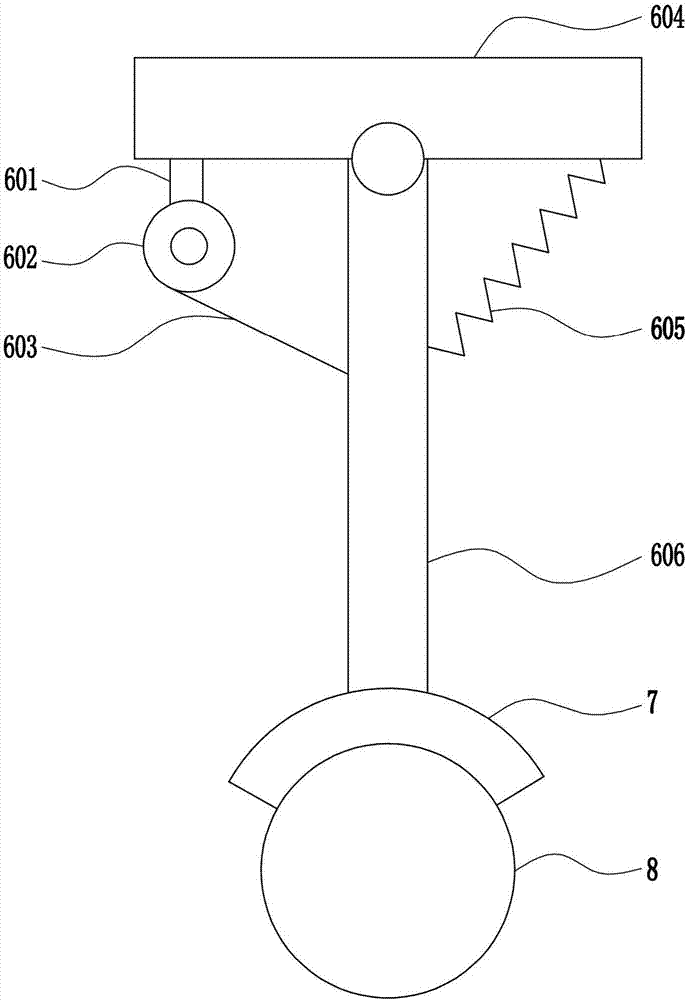
[0037]The rotating device 5 includes a first slider 501, a first connecting rod 502, a motor 503, an annular slide rail 504 and a top plate 505, the top of the support 4 is provided with a top plate 505, and the middle position of the bottom of the top plate 505...

Embodiment 3

[0039] An electric heating irradiation drying device, such as Figure 1-5 As shown, it includes placing a grid plate 2, a first pole 3, a support 4, a rotating device 5, a swing device 6, a lampshade 7 and a warm light 8, and the ground 19 is provided with a first pole 3 and a support 4, and The first pole 3 is located inside the support 4, the top of the first pole 3 is provided with a grid plate 2, the top of the support 4 is provided with a rotating device 5, the bottom of the rotating device 5 is provided with a swing device 6, and the bottom of the swing device 6 is provided with a lampshade 7 , The bottom of the lampshade 7 is provided with a warm light 8, and the warm light 8 is located above the grid plate 2.

[0040] The rotating device 5 includes a first slider 501, a first connecting rod 502, a motor 503, an annular slide rail 504 and a top plate 505, the top of the support 4 is provided with a top plate 505, and the middle position of the bottom of the top plate 50...


PUM


Abstract

The invention relates to a drying device, in particular to an electro-thermal irradiation drying device, and aims to provide the electro-thermal irradiation drying device. In order to solve the technical problem, the invention provides the electro-thermal irradiation drying device. The electro-thermal irradiation drying device comprises a placing mesh plate, first supporting rods, a bracket, a rotating device, a swing device and the like, wherein the first supporting rods and the bracket are arranged on the ground; the first supporting rods are located on the inner side of the bracket; the placing mesh plate is arranged at the tops of the first supporting rods; the rotating device is arranged at the top of the bracket; the swing device is arranged at the bottom of the rotating device; a lampshade is arranged at the bottom of the swing device; a warm light lamp is arranged at the bottom of the lampshade; and the warm light lamp is placed above the mesh plate. The electro-thermal irradiation drying device achieves high drying efficiency and more uniform drying; furthermore, the fixing effect on a material is better, so that the material cannot be blown away in a drying process, and an effect of longer service life is achieved; and the electro-thermal irradiation drying device is high in practicability and high in generalizability.

Description

technical field [0001] The invention relates to a drying device, in particular to an electric heating irradiation drying device. Background technique [0002] Drying refers to the process of removing the solvent to retain the solid content in a certain way, and usually refers to the process of passing hot air to evaporate and take away the water in the material. [0003] In daily life or industrial production, materials often contain some water, and these water needs to be removed. The current drying device has low drying efficiency, uneven drying, and poor fixing effect on materials. It is easy to be blown away, so it is urgent to develop an electric heating irradiation drying device with high drying efficiency, more uniform drying, and better fixing effect on materials. Contents of the invention [0004] (1) Technical problems to be solved [0005] The present invention overcomes that in life or industrial production, materials often contain some water, and these water...

Claims


Application Information

Patent Timeline
Patent Type & Authority Applications(China)
IPC IPC(8): F26B9/06F26B23/04F26B25/00
CPCF26B9/06F26B23/04F26B25/00
Inventor 钮芳琴钱聪沈凯
Owner 浙江聚业科技有限公司
Why Eureka
Try Eureka