
Illuminating lamp with rotating direction and position adjustable function for numerically-controlled machine tool

A technology of rotation direction and CNC machine tools, applied in the field of CNC machine tools, can solve the problems of inconvenient use of CNC machine tool lights, waste of people's time and physical strength, etc., and achieve the effect of compact structure, saving time and physical strength, and large irradiation range

Inactive Publication Date: 2018-05-08
刘青建
View PDF7 Cites 6 Cited by
  • Summary
  • Abstract
  • Description
  • Claims
  • Application Information

AI Technical Summary

Problems solved by technology

[0005] Aiming at the deficiencies of the prior art, the present invention provides a lighting lamp for numerically controlled machine tools that can adjust the rotation direction and position, which solves the problem that the traditional machine lighting lamps are generally adjusted by people manually turning the lighting lamp body. Because people manually adjust the lighting angle, it will waste people's time and physical strength, which will bring inconvenience to people when using the CNC machine tool lighting.

Method used


Image

  • Illuminating lamp with rotating direction and position adjustable function for numerically-controlled machine tool
  • Illuminating lamp with rotating direction and position adjustable function for numerically-controlled machine tool

Examples


Embodiment Construction

[0020] The technical solutions in the embodiments of the present invention will be clearly and completely described below in conjunction with the accompanying drawings in the embodiments of the present invention. Obviously, the described embodiments are only a part of the embodiments of the present invention, rather than all the embodiments. Based on the embodiments of the present invention, all other embodiments obtained by those of ordinary skill in the art without creative work shall fall within the protection scope of the present invention.

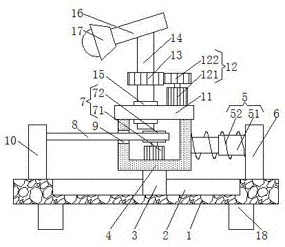
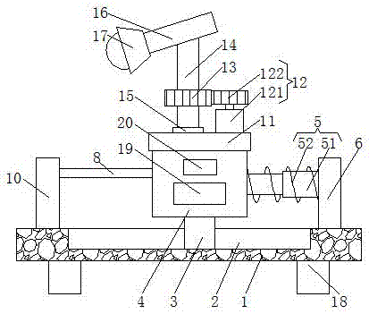
[0021] Such as Figure 1-2 As shown, the present invention provides a technical solution: a lighting lamp for a numerically controlled machine tool with adjustable rotation direction and position, comprising a base plate 1, four supporting legs 18 fixedly connected to the lower surface of the base plate 1, and four supporting legs 18 They are respectively located at the four corners of the lower surface of the bottom plate 1. Four suppor...


PUM


Abstract

The invention discloses an illuminating lamp with a rotating direction and position adjustable function for a numerically-controlled machine tool. The illuminating lamp comprises a bottom plate, a sliding groove is formed in the upper surface of the bottom plate, and a sliding block is slidably connected into the sliding groove. The upper surface of the sliding block is fixedly connected with thelower surface of a box, the right side face of the box is fixedly connected with the left side face of a first fixing plate through an elastic device, and the lower surface of the first fixing plate is fixedly connected with the upper surface of the bottom plate. According to the illuminating lamp with the rotating direction and position adjustable function for the numerically-controlled machine tool, by arranging a second driving device, an output shaft of a second motor in the second driving device rotates to drive a driving gear to rotate, the driving gear rotates to drive a driven gear torotate, the driven gear rotates to drive a rotary shaft to rotate, the rotary shaft drives an illuminating lamp body to rotate, thus the rotating angle of the illuminating lamp body can be directly adjusted, people do not need to manually adjust the illuminating angle, the time and physical power of people are saved, and thus convenience is brought to the situation that people use the illuminatinglamp of the numerically-controlled machine tool.

Description

Technical field [0001] The invention relates to the technical field of numerically controlled machine tools, in particular to a lighting lamp for numerically controlled machine tools which can adjust the rotation direction and position. Background technique [0002] CNC machine tool is the abbreviation of digital control machine tool, which is an automatic machine tool equipped with a program control system. The control system can logically process a program with a control code or other symbolic instructions, decode it, express it with coded numbers, and input it into the numerical control device through an information carrier. After arithmetic processing, the numerical control device sends out various control signals to control the action of the machine tool, and automatically process the parts according to the shape and size required by the drawing. The CNC machine tool solves the problem of complex, precise, small batch, and multi-variety parts processing. It is a flexible, h...

Claims


Application Information

Patent Timeline
IPC IPC(8): F21S9/02F21V21/15F21V21/16F21V21/22F21V21/30F21V21/34F21V23/00F21W131/403
CPCF21S9/02F21V21/15F21V21/16F21V21/22F21V21/30F21V21/34F21V23/003F21V23/02F21W2131/403
Inventor 刘青建
Owner 刘青建
Learn More