Over-temperature protection method, circuit and linear drive circuit with the circuit

An over-temperature protection circuit and over-temperature protection technology, applied in the field of electronics, can solve the problems of cumbersome operation, inaccurate temperature detection, inability to realize self-starting of power tubes, etc., and achieve the effect of timely protection and reducing inherent errors.

Active Publication Date: 2018-04-27
SILERGY SEMICON TECH (HANGZHOU) CO LTD
View PDF7 Cites 0 Cited by
  • Summary
  • Abstract
  • Description
  • Claims
  • Application Information

AI Technical Summary

Problems solved by technology

Although this method can avoid the problem of inaccurate temperature detection, it cannot realize the self-starting of the power tube, that is, it needs to be powered on again after each latch-off, and the operation is cumbersome.

Method used


Image

  • Over-temperature protection method, circuit and linear drive circuit with the circuit
  • Over-temperature protection method, circuit and linear drive circuit with the circuit
  • Over-temperature protection method, circuit and linear drive circuit with the circuit

Examples


Embodiment 1

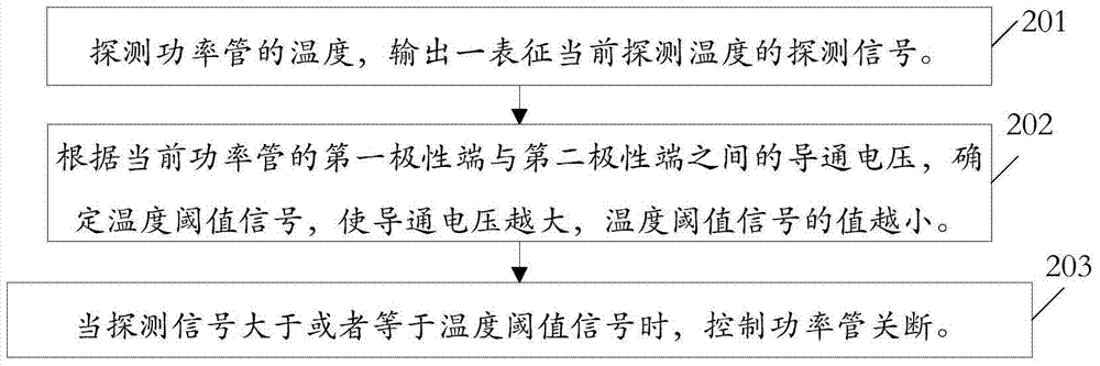
[0054] figure 2 For a schematic flow chart of a power tube over-temperature protection method provided in this embodiment, see figure 2 As shown, the method mainly includes the following steps:

[0055] Step 201: Detect the temperature of the power tube, and output a detection signal representing the currently detected temperature.

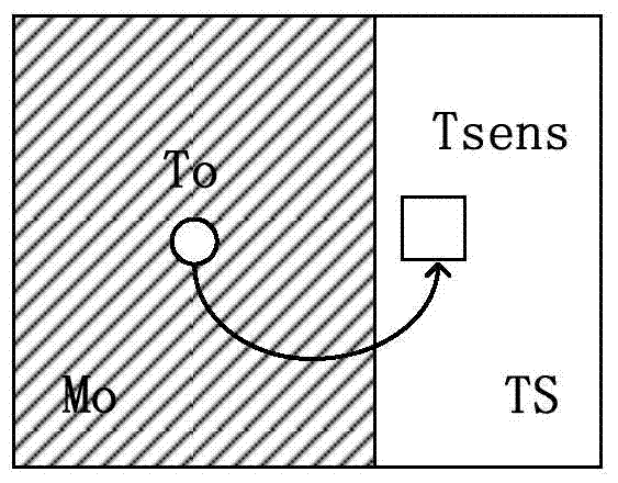
[0056] In this embodiment, the temperature of the power tube is detected to obtain a detection temperature (denoted as T sens ), and according to the detection temperature T sens Output one represents the current detection temperature T sens The probe signal S temp , so that the detection temperature T sens The higher the corresponding detection signal S temp higher.

[0057] As an illustration of this embodiment, the temperature of the power tube can be detected by the temperature sensing unit, and the detected temperature T sens The probe signal S temp It can be a voltage signal, that is, the temperature detected by the sensor in the ...

Embodiment 2

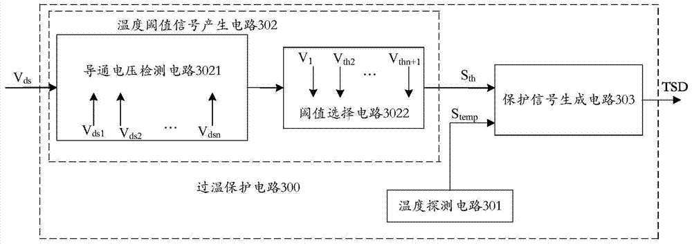
[0077] image 3 , 4 For the schematic diagram of the circuit principle of a power tube over-temperature protection circuit provided in Embodiment 1, see image 3 As shown, it mainly includes: a temperature detection circuit 301 , a temperature threshold signal generation circuit 302 and a protection signal generation circuit 303 . Its connection relationship and working principle are as follows:

[0078] Wherein, the temperature detecting circuit 301 detects the temperature of the power tube, and outputs a signal representing the detected temperature T sens The probe signal S temp . As an illustration of this embodiment, the temperature detection circuit 301 may include a temperature sensing unit to detect the temperature of the protected power tube.

[0079] The temperature threshold signal generating circuit 302 is based on the conduction voltage V between the first polarity terminal and the second polarity terminal of the power tube ds , the output temperature thresho...

Embodiment 3

[0099] In this embodiment, the Figure 5 The power tube over-temperature protection circuit 300 is used as an example in the linear drive circuit shown, and the implementation of the power tube over-temperature protection circuit is further described.

[0100] see Figure 5 As shown, the linear drive circuit of this embodiment mainly includes a main power stage circuit, and the main power stage circuit includes a power transistor M5 and an over-temperature protection circuit 300 disposed in the main power circuit.

[0101] see Figure 5 As shown, the first polarity terminal of the power tube M5 is coupled to the DC voltage input terminal Vout of the linear drive circuit through the load, and the second polarity terminal is coupled to the ground terminal through the detection resistor Rs, so that the first polarity of the power tube M5 flows through the power tube M5. The currents at the polarity terminal and the second polarity terminal are output currents of the linear driv...


PUM


Abstract

An over-temperature protection method, a circuit, and a linear drive circuit with the circuit. The over-temperature protection method of a power tube includes: according to the conduction voltage between the first polarity end and the second polarity end of the power tube , determine the temperature threshold signal, so that the larger the conduction voltage, the smaller the value of the temperature threshold signal; detect the current temperature of the power tube to obtain a detection signal representing the temperature; when the detection signal When it is greater than or equal to the temperature threshold signal, the power tube is controlled to be turned off. The technical scheme protects the power tube in a more timely and reliable manner.

Description

technical field [0001] The invention relates to the field of electronics, in particular to an over-temperature protection method, a circuit and a linear drive circuit with the circuit. Background technique [0002] In the power supply circuit that outputs voltage to the load through the power tube connected between the power supply terminal and the load, when the load is short-circuited, the voltage on the power tube connected in series with the load between the power supply terminal and the ground terminal in these circuits will change. Large, so that the power Po that the power tube bears is too large, and then the temperature of the power tube rises, and the greater the power it bears, the higher the temperature rises. When the temperature of the power tube rises to a certain temperature, it may be Cause the power tube to be burnt out. [0003] In order to avoid the above situation from happening, if figure 1 As shown, one approach in the prior art is to detect the temp...

Claims


Application Information

Patent Timeline
Patent Type & Authority Patents(China)
IPC IPC(8): H02H7/10H02H5/04H02M1/08
CPCG05F1/569H01H37/32
Inventor 金津
Owner SILERGY SEMICON TECH (HANGZHOU) CO LTD
Why Eureka
Try Eureka