Rotavator with gear exchange unit
A technology of exchange device and rotary tiller, applied in the direction of gear transmission device, transmission device, belt/chain/gear, etc., can solve the problems of unresolved, unresolved soil state, addition and subtraction of power, etc., to improve the convenience of parts storage performance, improve work adaptability, and effectively cultivate the effect of work
- Summary
- Abstract
- Description
- Claims
- Application Information
AI Technical Summary
Problems solved by technology
Method used
Image

Examples
Embodiment Construction
[0023] Hereinafter, preferred embodiments of the present invention will be described in detail with reference to the accompanying drawings. Also, in describing the present invention, when a specific description of a related known function or structure may unnecessarily obscure the gist of the present invention, the detailed description will be omitted.
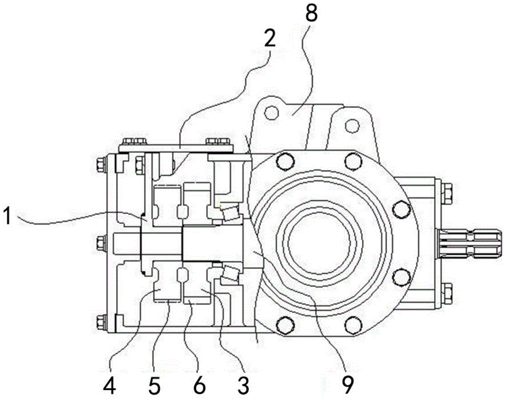
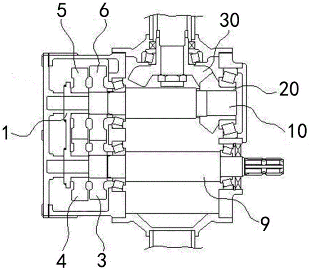
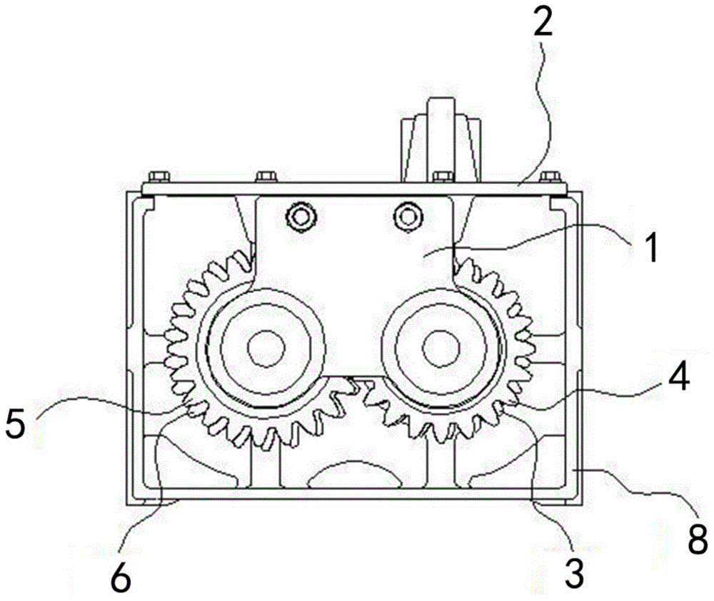
[0024] Figure 1 to Figure 5 The shown rotary tiller equipped with a gear exchange device of the present invention includes a PTO shaft 9 that outputs the power of the tractor, and receives power through the connection between the input shaft 10 and the PTO shaft 9. The rotary tiller is characterized in that the The PTO shaft 9 and the input shaft 10 are arranged in the gearbox 8 in parallel, the first conversion gear 3 is installed on the PTO shaft 9, and the first driven gear 6 is installed on the input shaft 10. The two mesh with each other, the second conversion gear 4 is installed on the side of the first conversion gear...
PUM
 Abstract
Description
Claims
Application Information