A Friction Welding Control System

A control system and friction welding technology, applied in the field of friction welding, can solve the problems of high energy consumption, high contact resistance and high labor cost in electrolytic aluminum production, and achieve the effect of reducing labor cost, simplifying welding process and reducing the number of workers

Active Publication Date: 2017-02-22
LANZHOU UNIVERSITY OF TECHNOLOGY
View PDF8 Cites 0 Cited by
  • Summary
  • Abstract
  • Description
  • Claims
  • Application Information

AI Technical Summary

Problems solved by technology

[0003] In order to solve the problem of cumbersome welding process and high labor cost when using the explosive welding process to weld the anode conductive device, and the anode conductive device obtained by welding has a large contact resistance when applied to the production of electrolytic aluminum, which leads to the problem of large energy consumption in the production of electrolytic aluminum, The invention proposes a friction welding control system to simplify the welding process, reduce labor costs, and reduce energy consumption in the production process of electrolytic aluminum

Method used


Image

  • A Friction Welding Control System
  • A Friction Welding Control System
  • A Friction Welding Control System

Examples


Embodiment 1

[0029] Such as image 3 As shown, the friction welding control system includes a control unit 20 , a speed regulating unit 22 , a spindle motor 21 , a soft starter 24 and a power unit 23 . The speed regulation unit 22 is respectively connected with the control unit 20 and the spindle motor 21 , and the speed regulation unit 22 is used for receiving the speed regulation instruction sent by the control unit 20 and adjusting the rotation speed of the spindle motor according to the speed regulation instruction. The soft starter 24 is connected with the control unit 20 and the power unit 23 respectively, and the soft starter 24 is used for receiving the starting command sent by the control unit 20 and starting the power unit 23 according to the starting command. Wherein, the control unit 20 is a programmable logic controller (ProgrammableLogic Controller, hereinafter referred to as PLC), and the speed regulating unit 22 is a frequency converter.

[0030] The workflow of the fricti...

Embodiment 2

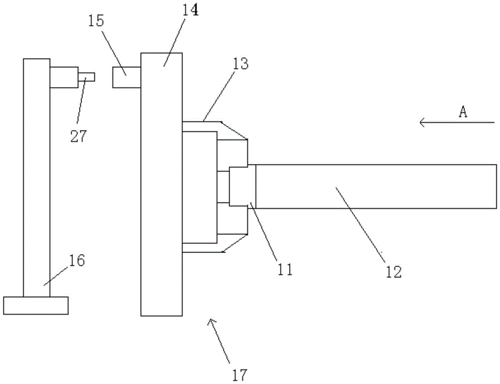
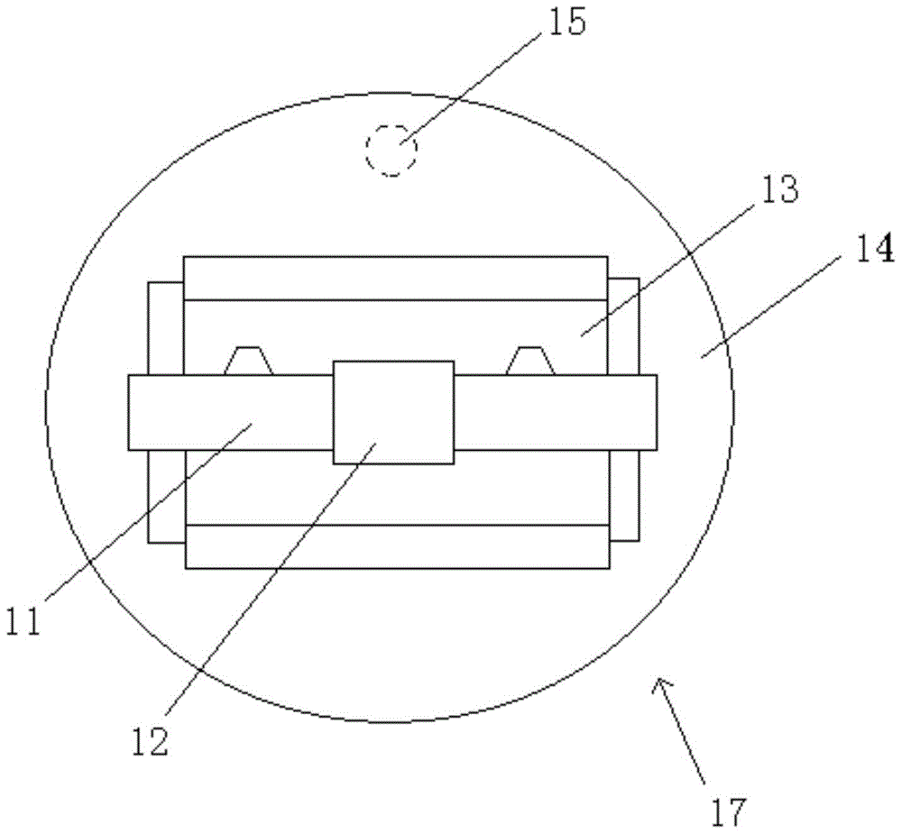
[0036] Such as Figure 5 As shown, the difference from the first embodiment is that the friction welding control system of the second embodiment also includes a positioning position unit 27, which is connected to the speed regulating unit 22, and the positioning position unit 27 is a proximity switch. Such as Figure 2a and Figure 2bAs shown, the steel claw clamp 17 includes a clamping port 13 and a disc 14, the clamping port 13 is fixedly connected to the disc 14, the clamping port 13 clamps the steel claw 11, and the positioning position unit 27 is installed on the base 16. During the friction welding process, the disc 14 and the clamping port 13 rotate synchronously under the drive of the spindle motor 21. A cylindrical metal bump 15 is arranged on the disc 14 at the direction of 12 o'clock. During the rotation of the disc 14, the cylindrical metal bump 15 Every time 15 passes the positioning position unit 27, that is, every time the steel jaw 11 rotates once, the positi...

Embodiment 3

[0042] Such as Figure 7 As shown, the friction welding control system also includes a steel claw information unit 25 , an aluminum guide rod information unit 26 and a speed feedback unit 28 .

[0043] The steel claw information unit 25 is connected with the speed reducer rear end of the control unit 20 and the main shaft motor 21 respectively, and the steel claw information unit 25 directly collects the position and speed information of the steel claw, and sends this information to the control unit 20, and the control unit 20 according to The position and speed information of the steel claw calculate the number of rotations of the steel claw and the specific angle of the current circle where the steel claw is located, so that the control unit 20 first detects the position and speed information of the steel claw before sending a positioning command to the speed regulating unit 22, To ensure that the steel claw is in the same position before each positioning command is sent, th...


PUM

PropertyMeasurementUnit
electrical resistivityaaaaaaaaaa
electrical resistanceaaaaaaaaaa

Abstract

The invention belongs to the technical field of friction welding. The invention provides a friction welding control system, aiming at solving the problems that the procedures of a welding process are complicated and the manpower cost is high when an explosion welding process is used for welding an anode conductive device, the contact resistance is great when the welded anode conductive device is used for producing electrolytic aluminum so that the production energy consumption of the electrolytic aluminum is great. The system comprises a control unit, a speed regulating unit, a main shaft motor, a soft starter and a power unit, wherein the speed regulating unit is connected with the control unit and the main shaft motor respectively; the speed regulating unit is used for receiving a speed regulating instruction sent by the control unit, and controlling the rotary speed of the main shaft motor according to the speed regulating instruction; the soft starter is connected with the control unit and the power unit respectively; the soft starter is used for receiving a starting instruction sent by the control unit, and starting the power unit according to the starting instruction. With the adoption of the friction welding control system, the welded anode conductive device has the advantage of being capable of obviously reducing the energy consumption in an electrolytic aluminum production process.

Description

technical field [0001] The invention belongs to the technical field of friction welding, and in particular relates to a friction welding control system. Background technique [0002] Such as figure 1 As shown, the anode conductive device 10 of the prebaked aluminum electrolytic cell includes a steel claw 11 and an aluminum guide rod 12. When the cross-sectional size of the aluminum guide rod 12 is 130mm×130mm, the mass of the aluminum guide rod 12 is 147Kg, corresponding to the weight of the steel claw 11. The mass is 298Kg. At present, the steel claw 11 and the aluminum guide rod 12 are usually welded by an explosive welding process. In the explosive welding process, a composite explosive welding sheet needs to be used. Workers are required to manually weld the aluminum guide rod 12 and the aluminum end of the explosive welding sheet, and then weld the steel The claw 11 is manually welded to the steel end of the explosive welding sheet. The entire welding process is cumbe...

Claims


Application Information

Patent Timeline
Patent Type & Authority Patents(China)
IPC IPC(8): B23K20/12
CPCB23K20/123
Inventor 冯小林毛海杰刘满强芮执元李鄂民辛舟罗德春张昌青陈辉刘朝荣裴喜平张玮于振燕李经纬
Owner LANZHOU UNIVERSITY OF TECHNOLOGY
Why Eureka
Try Eureka