Direct feeding shaft servo parameter optimization method based on dynamic stiffness evaluation
An optimization method and dynamic stiffness technology, applied in the direction of instruments, computer control, simulators, etc., can solve the problems of lack of guidance rules, inability to accurately judge the resonance point of the feed shaft, and inability to determine the mechanical working frequency band, etc., to improve the anti-interference performance , Increase the effect of direct feed axis without overshooting frequency band
Inactive Publication Date: 2015-08-12
UNIV OF SHANGHAI FOR SCI & TECH
View PDF4 Cites 4 Cited by
- Summary
- Abstract
- Description
- Claims
- Application Information
AI Technical Summary
Problems solved by technology
However, when using this method to optimize the servo parameters, there are many deficiencies: when there are multiple overshoot points, it is often impossible to accurately judge the resonance point of the feed axis; , it is impossible to determin
Method used
View moreImage
Smart ImageViewing Examples
Examples
 PUM
 Abstract
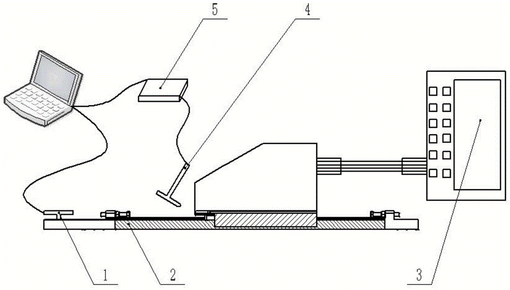
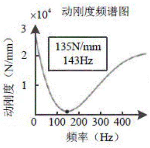
The invention relates to a direct feeding shaft servo parameter optimization method based on dynamic stiffness evaluation, and a system. The direct feeding shaft is the concrete object. The method comprises the steps of confirming system performance parameter, and ensuring the normal working of a servo system of a linear motor; gradually increasing speed ring gain, and reading frequency range of each overshoot point of speed ring Bode diagram and the bandwidth data. Through the dynamic stiffness measuring method, the dynamic stiffness frequency spectrogram can be calculated, and the resonance frequency range of the servo system can be determined. With the Bode diagram, the resonance frequency range bandwidth can be determined, and a corresponding electronic filter is disposed in the servo system, and thereby the resonance frequency range can be inhibited. The servo parameter optimization method based on dynamic stiffness evaluation can effectively optimize the direct feeding shaft servo parameter.
Description
technical field [0001] The invention relates to a dynamic stiffness testing method and a servo parameter optimization method, in particular to a parameter optimization method of a direct feed axis. Background technique [0002] Linear motors have the advantages of fast response, high positioning accuracy, no travel limit, and high efficiency. In high-speed and high-precision motion, the feed shaft driven by linear motors does not require intermediate transmission links, and is an ideal feed for realizing direct drive technology. Drive mechanism. However, the unique "zero transmission" mode of this direct drive feed shaft makes load changes, internal disturbances and external disturbances directly act on the working platform without intermediate transmission links, which hinders the further exertion of the advantages of linear motors and also limits their servo performance. Control brings great difficulty. [0003] The technology of improving the anti-interference performan...
Claims
Login to View More Application Information
Patent Timeline
 IPC IPC(8): G05B19/401
CPCG05B19/401
Inventor 林献坤李裴祥李田田
Owner UNIV OF SHANGHAI FOR SCI & TECH
Features
- R&D
- Intellectual Property
- Life Sciences
- Materials
- Tech Scout
- Unparalleled Data Quality
- Higher Quality Content
- 60% Fewer Hallucinations
Learn More Browse by: Latest US Patents, China's latest patents, Technical Efficacy Thesaurus, Application Domain, Technology Topic, Popular Technical Reports.
© 2025 PatSnap. All rights reserved.Legal|Privacy policy|Modern Slavery Act Transparency Statement|Sitemap|About US| Contact US: help@patsnap.com


