
Wall-controlled dimming method for LED lamp

A LED lamp and dimming technology, applied in the direction of light source, electric light source, electroluminescent light source, etc., can solve the problems of high cost, large number of remote controls, and time requirements for switching actions, and achieve the effect of short time

Inactive Publication Date: 2015-08-12
HUNAN UNIV OF TECH
View PDF8 Cites 0 Cited by
  • Summary
  • Abstract
  • Description
  • Claims
  • Application Information

AI Technical Summary

Problems solved by technology

The LED light control circuit is equipped with a remote control receiving device, and the LED light can be dimmed step by step or steplessly dimmable through the remote control. The disadvantage is that one LED light needs to be equipped with a remote control, resulting in a large number of remote controls and troublesome management. , the cost is also high
However, this method can only provide 4 levels of adjustable brightness of LED lights, and the switch action has a time requirement

Method used


Image

  • Wall-controlled dimming method for LED lamp
  • Wall-controlled dimming method for LED lamp
  • Wall-controlled dimming method for LED lamp

Examples


Embodiment Construction

[0053]The present invention will be described in further detail below with reference to the accompanying drawings and examples, but the embodiments of the present invention are not limited thereto.

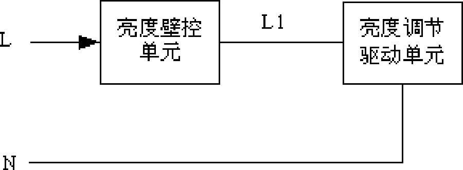
[0054] The structure of an embodiment of a LED lamp single live wire dimming circuit that realizes the method of the present invention is as follows: figure 1 As shown, it consists of a brightness wall control unit and a brightness adjustment drive unit connected in series. The brightness wall control unit has a single live line L input and a single live line L1 output; the brightness adjustment drive unit has a live line L1 input and a neutral line N output.

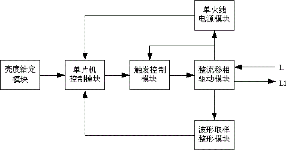
[0055] The structure of the brightness wall control unit is as follows figure 2 As shown, it consists of a single live wire power supply module, a rectification phase-shifting drive module, a waveform sampling and shaping module, a single-chip microcomputer control module, a trigger control module, and a given brightness ...


PUM


Abstract

A wall-controlled dimming method for an LED lamp is dimmed by an LED lamp single-live-wire dimming circuit which is composed of a brightness wall controlling unit and a brightness adjustment driving unit. When brightness adjustment is required, the brightness wall controlling unit controls and changes the phase-shift angle of a single-live-wire output voltage waveform for transmitting a brightness control signal. In the brightness control signal, a brightness grade is represented by the number of continuous single-phase sinusoidal half-waves with specific phase shift angles. The brightness adjustment driving unit changes the brightness of the LED lamp according to the brightness grade in the brightness control signal. When the brightness wall controlling unit transmits the brightness control signal, the number of the half-waves which are continuously output from the single-live-wire output end and have the same phase shift angle is the brightness grade of the brightness control signal. The LED lamp dimming method can be used for replacement and upgrading of a common illuminating lamp which is controlled by the single live wire.

Description

technical field [0001] The invention relates to a lighting lamp technology, in particular to a LED lamp wall control dimming method. Background technique [0002] Due to the nonlinear characteristics of LED lamps, the brightness of LED lamps cannot be realized by adjusting the voltage. [0003] When using a controllable constant current source to adjust the brightness of the LED lamp, the change of the working current will cause the color shift of the LED lamp. At the same time, the load current of the LED lamp becomes very low under low brightness, which will make the controllable constant current source The lower the efficiency and the higher the temperature rise, the greater the power consumption on the driver chip will be, which will damage the life of the constant current source and the LED light source. [0004] Using PWM (pulse width modulation) dimming method to control the brightness of LED lights can avoid the problems caused by voltage regulation and current regu...

Claims


Application Information

Patent Timeline
Patent Type & Authority Applications(China)
IPC IPC(8): H05B37/02H05B44/00
CPCH05B45/37Y02B20/30
Inventor 凌云陈刚孔玲爽郭艳杰曾红兵
Owner HUNAN UNIV OF TECH
Learn More