Electrostatic atomizer

An electrostatic spray and mist technology, applied in electrostatic spray devices, spray discharge devices, spray devices, etc., can solve problems such as liquid leakage of electrostatic spray device 100

Inactive Publication Date: 2015-08-12
SUMITOMO CHEM CO LTD
View PDF5 Cites 0 Cited by
  • Summary
  • Abstract
  • Description
  • Claims
  • Application Information

AI Technical Summary

Problems solved by technology

[0004] However, in the conventional electrostatic spray device 100, downsizing is sometimes emphasized, and simplification of the structure is also required.
Therefore, in the electrostatic spraying device 100, the liquid level holding hole 105 and the air hole 106 communicate with each other through the linear air path 107, and there is a fear that the liquid 104 may fall from The liquid level holding hole 105 moves to the air hole 106, causing the electrostatic spray device 100 to leak liquid to the outside.

Method used


Image

  • Electrostatic atomizer
  • Electrostatic atomizer
  • Electrostatic atomizer

Examples


Embodiment 1

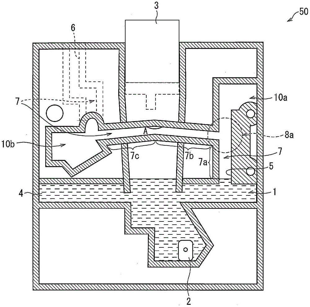
[0080] in turn figure 1 The electrostatic spray device 50 was laid down in four directions, front, back, left, and right, and whether there was any liquid leakage was confirmed, and then it was restored to the original state, thereby confirming whether there was any liquid leakage. It should be noted that, in the electrostatic spray device 50, there are two places with a capacity of 200mm 3 In the liquid holding space 10, the angle A of the air path 7 is 170°, and in a part of the air path 7, an inclination of 5° is provided to the left and right, respectively.

[0081] The setting conditions of the electrostatic spray device 50 are as follows.

[0082] Capacity of chamber 1: 200mm 3

[0083] The diameter of the liquid level maintenance hole 5 (four corners): 1mm

[0084] The diameter of the air hole 6 (round): 1mm

[0085] Length of air path 7 (shaft length): 26mm

[0086] The linear distance between the liquid level maintenance hole 5 and the air hole 6: 11mm

[0087...


PUM


Abstract

An electrostatic atomizer (50) is provided with a chamber (1) and an air passage (7) which connects a liquid level maintaining hole (5) and an air hole (6) which supplies air to the chamber (1) from the outside of the electrostatic atomizer (50). The electrostatic atomizer (50) is configured in such a manner that the supply of liquid from a liquid supply section (3) to the chamber (1) is stopped when the liquid level maintaining hole (5) is closed. The air passage (7) has a bend section (8). A space (10) for holding liquid is formed in the air passage (7).

Description

technical field [0001] The present invention relates to an electrostatic spraying device in which liquid leakage of sprayed liquid hardly occurs. Background technique [0002] Conventionally, a spray device that sprays liquid in a container from a spray unit has been used in a wide range of fields. As such a spraying device, there is known an electrostatic spraying device that atomizes a liquid using electrohydrodynamics (EHD: Electro Hydrodynamics) and then sprays it. In this electrostatic spraying device, an electric field is formed near the tip of the spraying section, and the liquid at the tip of the spraying section is atomized and sprayed by the electric field. Figure 6 Such an electrostatic spray device is shown. [0003] Figure 6 The electrostatic spraying device 100 of the present invention includes a chamber 101 , a spray unit 102 , and a liquid supply unit 103 , and the liquid 104 supplied from the liquid supply unit 103 to the chamber 101 is sprayed by the spr...

Claims


Application Information

Patent Timeline
Patent Type & Authority Applications(China)
IPC IPC(8): B05B5/16B05B5/057A61M11/00
CPCB05B5/16A61M2205/21A61M15/02A61M11/00B05B5/057B05B5/0255B05B5/03
Inventor 佐佐木崇窦文清
Owner SUMITOMO CHEM CO LTD
Why Eureka
Try Eureka