Appearance structural part applied to intelligent terminal products and manufacturing method thereof

A technology of intelligent terminals and manufacturing methods, applied in the direction of layered products, metal layered products, chemical instruments and methods, etc., can solve problems such as poor connection strength, large flatness, and low blank yield

Inactive Publication Date: 2017-03-15
深圳市华欣永业科技有限公司 +1
View PDF4 Cites 0 Cited by
  • Summary
  • Abstract
  • Description
  • Claims
  • Application Information

AI Technical Summary

Problems solved by technology

[0002] With the rapid development of electronic products, smart terminals such as smart wearable devices, tablet computers, and smart homes are becoming more and more popular, and people have higher and higher requirements for the appearance of smart terminals. At present, many companies have carried out a lot of research on this Research, in the prior art, some surface metal parts with concave cavity or binding features are assembled with internal features or complex internal structural parts through injection mold injection. This method is suitable for internal features or complex internal structural parts Easy, but the injection molded plastic internal features or complex internal structural parts have poor strength, and at the junction of metal and plastic, due to the plastic internal features or complex internal structural parts cooling and shrinking, there are internal stresses that are difficult to eliminate, resulting in the structure Deformation; In addition, due to the strength of the plastic, the internal characteristics of the plastic formed by injection molding or the strength of the complex internal structural parts of the plastic can no longer meet the thinning and refined requirements of the appearance and structural parts of today's smart terminals
[0003] In addition, there are existing schemes that completely use metal materials to prepare appearance structural parts. The metal outer shell with high appearance requirements is formed by metal stamping, forging or machining, and the inner shell with complex structure that does not have high appearance requirements It is formed by metal die-casting, which meets the thinning and refined requirements of today's intelligent terminal appearance structural parts, but there are problems such as excessive internal stress at the junction of the inner and outer layers, product warping and deformation, and excessive flatness; and as Over time, defects such as cracks or cracks will occur at the junction of the inner and outer layers
The gate of the die-casting mold structure it adopts is located on the side of the product. The vector direction of the pressure during the die-casting process is from the outer side of one side of the product to the inner side of the opposite side. The eddy current formed during the die-casting process exists in the feed On the inner side of the edge, the strong die-casting pressure will deform the outermost metal structure or cause flow marks on the outermost layer, and make the connection strength of the two layers of materials very poor, requiring more CNC processing time in the later stage
Moreover, the yield rate of blanks adopting this technical solution is very low, below 50%.

Method used


Image

  • Appearance structural part applied to intelligent terminal products and manufacturing method thereof
  • Appearance structural part applied to intelligent terminal products and manufacturing method thereof
  • Appearance structural part applied to intelligent terminal products and manufacturing method thereof

Examples


Embodiment 1

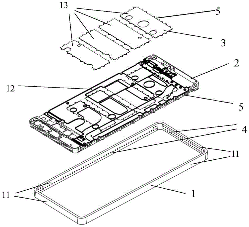
[0061] like figure 1 As shown, a metal mobile phone casing is divided into three layers using the mosaic module principle, which are the outermost layer outer frame 1, the middle layer 2 and the inner layer 3, and the length and width of the opposite outer layer in the two adjacent layers are respectively greater than the opposite The length and width of the inner layer, the outermost outer frame 1 is made of stainless steel, the middle layer 2 is made of aluminum alloy, and the inner layer 3 is made of aluminum alloy.

[0062] The outermost outer frame 1 is formed by metal stamping, forging or extrusion, and the outermost outer frame 1 includes four outer frames 11, and the horizontal width of the outer frames 11 is 0.3-3mm. The inner wall of the frame 11 is provided with a plurality of pits 4, and the pits 4 are formed by mechanical processing or chemical and physical treatment; the middle layer 2 and the inner layer 3 are divided and designed according to the mosaic module ...

Embodiment 2

[0070] The structure of the mobile phone shell of this example is the same as that of Example 1. The difference between this example and Example 1 is that the manufacturing method is different, and the materials of the outermost outer frame 1, the middle layer 2 and the inner layer 3 are also different; The outer frame 1 is made of stainless steel, the middle layer 2 is made of aluminum alloy, and the inner layer 3 is made of aluminum alloy.

[0071] The mobile phone shell of this example is prepared by the following steps:

[0072] Step S1: forming the outermost outer frame 1 by stamping, forging, extrusion or machining; forming a plurality of pits 4 on the inner wall of the outermost outer frame 1 by chemical etching;

[0073] Step S2: Put the outermost outer frame 1 into the mold, and mold the middle layer 2 on the outermost outer frame 1 by die-casting or casting to obtain the outer two layers of the composite mobile phone case; The edge forming concave cavity 5;

[0074...

Embodiment 3

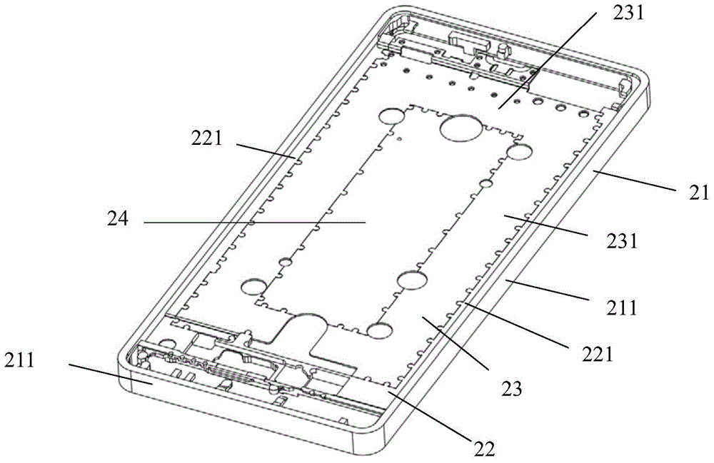
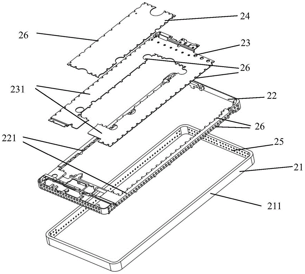
[0079] like figure 2 and image 3 As shown, a metal flat shell is divided into four layers by using the mosaic module principle, and from the outside to the inside are the outermost frame 21, the second layer 22, the third layer 23 and the fourth layer 24; two adjacent layers The length and width of the relative outer layer are respectively greater than the length and width of the relative inner layer, the outermost outer frame 21 is made of forged aluminum alloy, rolled aluminum alloy or profiled aluminum alloy, and the second layer 22 and the third layer 23 are made of aluminum alloy 23. The fourth layer 24 is made of magnesium alloy.

[0080] The outermost outer frame 21 is formed by metal stamping, forging or extrusion, and the outermost outer frame 21 includes four frames 211, the horizontal width of the frame 211 is 0.3 ~ 3mm, the frame 211 The inner wall is provided with a plurality of pits 26, and the pits 26 are formed by mechanical processing or chemical and physi...


PUM

PropertyMeasurementUnit
lengthaaaaaaaaaa
thicknessaaaaaaaaaa
widthaaaaaaaaaa

Abstract

The invention provides an appearance structural member applied to an intelligent terminal product and a manufacturing method of the appearance structural member. The appearance structural member comprises at least three metal structure layers, wherein the metal structure layers comprise an outermost metal structure layer and metal structure inner-layers from outside to inside by using a mosaic module principle, and the metal structure inner-layers at least comprise a second metal structure layer and a third metal structure layer; in every two adjacent metal structure layers, the length and the width of the relatively outer layer are greater than those of the relatively inner layer, and every two adjacent layers are connected together by pressure casting or molten metal casting and fusion; each metal structure layer is formed by gradation; except the outermost metal structure layer, the melting point of the firstly formed metal structure inner-layer is not more than that of the later formed metal structure inner-layer. The appearance structural member adopting the technical scheme is attractive in appearance, shrinkage distortion is reduced, the product percent of pass is improved, and meanwhile the failure risks of product distortion, junction cracking and the like caused by subsequent stress release are lowered.

Description

technical field [0001] The invention belongs to the technical field of production of intelligent terminal appearance structural parts, and relates to an appearance structural part of an intelligent terminal product and a manufacturing method thereof, in particular to a metal appearance structural part of an intelligent terminal product and a manufacturing method thereof. Background technique [0002] With the rapid development of electronic products, smart terminals such as smart wearable devices, tablet computers, and smart homes are becoming more and more popular, and people have higher and higher requirements for the appearance of smart terminals. At present, many companies have carried out a lot of research on this Research, in the prior art, some surface metal parts with concave cavity or binding features are assembled with internal features or complex internal structural parts through injection mold injection. This method is suitable for internal features or complex int...

Claims


Application Information

Patent Timeline
Patent Type & Authority Patents(China)
IPC IPC(8): B32B15/01B32B7/10B32B37/04B32B37/15B32B38/00
CPCB32B7/10B32B15/012B32B37/04B32B37/156B32B38/0012B32B2038/0028
Inventor 吴宇峰董艳
Owner 深圳市华欣永业科技有限公司
Why Eureka
Try Eureka