A gravure printing machine anti-condensation circulation ink return system

An anti-condensation and recycling technology, which is applied to gravure rotary printing machines, printing machines, rotary printing machines, etc., can solve the problems of slow flow of surface ink, increase of enterprise cost, stagnation, etc., and achieve improvement of ink skin phenomenon and structure Concise and reliable, ensuring non-modifying effects

Active Publication Date: 2017-09-12
HUANGSHAN NOVEL
View PDF9 Cites 1 Cited by
  • Summary
  • Abstract
  • Description
  • Claims
  • Application Information

AI Technical Summary

Problems solved by technology

The defect of the current above-mentioned structure is that: since the ink pump circulates and draws the ink in the ink cavity by bottom-end extraction, the bottom ink in the ink cavity flows fast while the surface ink flows slowly or even stagnates.
Moreover, because the ink supply system of the equipment is usually designed so that the lower half of the roller surface of the ink supply roller is directly immersed in the ink of the ink fountain cart, the ink skin is easily adhered to the roller surface of the ink supply roller and then brought to the printing film, forming a large piece Stains, destroying the uniformity of the original pattern or color on the printing film, forming waste products
Even a small amount of ink skin adhesion will form spots on the printed matter, which will affect the quality of the printed matter, and even cause the printed matter to be scrapped, wasting a lot of raw materials, destroying the smoothness of the printed matter production process, and increasing the cost of the enterprise

Method used


Image

  • A gravure printing machine anti-condensation circulation ink return system
  • A gravure printing machine anti-condensation circulation ink return system
  • A gravure printing machine anti-condensation circulation ink return system

Examples


Embodiment Construction

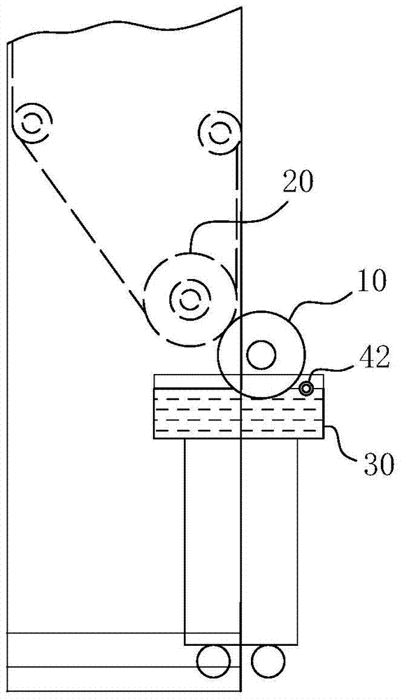
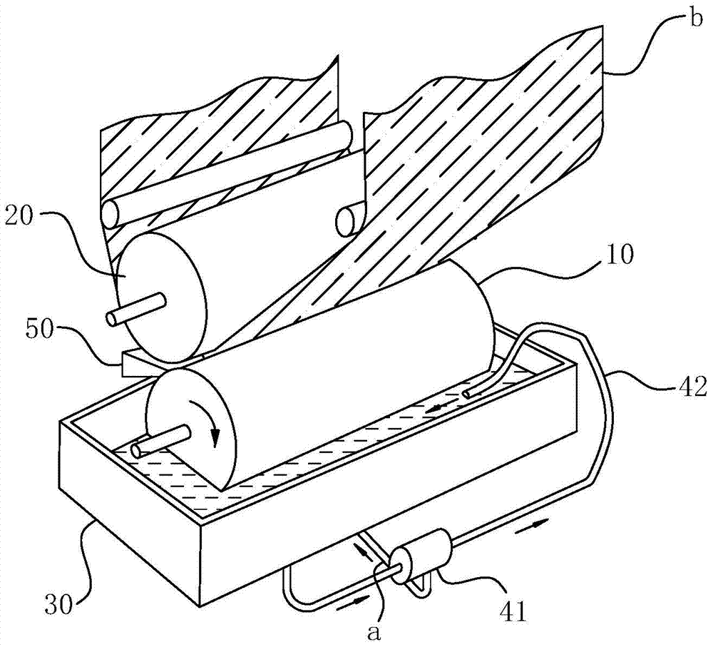
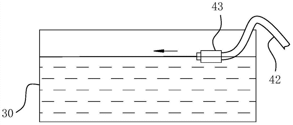
[0022] For ease of understanding, combined here Figure 1-5 Concrete structure of the present invention and working state are described further as follows:

[0023] The working structure of the present invention is as figure 1 As shown, it includes an ink tray 30 that is in the shape of a tank and can be placed on a base or a trolley. The hopper structure of the ink tray 30 constitutes a storage bin for storing ink. An inking roller 10 for cooperating with the embossing roller 20 of the gravure printing machine is erected above the opening of the ink tray 30 . Wherein the inking roller 10 is located below, and part of the roller surface can be set to be immersed below the ink surface of the ink tray 30 . The external ink is pumped in through the ink pump 41, and is directly sprayed on the surface of the ink delivery roller 10 through the ink outlet pipeline a connected to the outlet of the ink pump 41. First, the ink is smoothed evenly by the scraper 50 on the surface of the...


PUM


Abstract

The invention belongs to the technical field of gravure printing equipment, and in particular relates to a gravure printing machine anti-condensation circulation ink return system which can effectively improve the ink skin condensation phenomenon of the current gravure printing machine. The present invention includes an inking roller and an embossing roller, an ink tray for receiving and storing excess ink at the inking roller is arranged under the inking roller, and the ink return system also includes a doctor blade arranged at the surface of the inking roller and a An ink supply assembly for supplying ink to the roller surface of the ink feed roller; the ink supply assembly includes an ink pump, the ink pump inlet end is connected to the ink tray and / or the external ink tank, and the ink outlet end is arranged to point to the roller surface of the ink feed roller; The ink return system also includes a branch ink tube, the inlet end of the branch ink tube is connected to the ink outlet end of the ink pump, and the outlet end of the branch ink tube extends into the ink tray and the height of the tube end of the outlet end is equal to the height of the inner ink surface. The orientation is set horizontally. The invention has low realization cost and can effectively improve the coagulation and adhesion phenomenon of the ink skin caused by the poor flow of surface ink in the traditional gravure printing machine.

Description

technical field [0001] The invention belongs to the technical field of gravure printing equipment, and in particular relates to a gravure printing machine anti-condensation circulation ink return system which can effectively improve the ink skin condensation phenomenon of the current gravure printing machine. Background technique [0002] The gravure printing machine is widely used in the film printing industry due to its advantages of thick ink layer, uniform ink color and long service life. When the gravure printing machine performs film printing work, it is necessary to insert the ink fountain cart equipped with the ink feeding roller into the socket reserved on the gravure printing machine, and rely on the roller surface cooperation between the ink feeding roller and the embossing roller on the main machine of the gravure printing machine . Afterwards, the printing film to be printed is pasted and passed through the gap between the above two rollers. During the progress...

Claims


Application Information

Patent Timeline
Patent Type & Authority Patents(China)
IPC IPC(8): B41F9/06B41F31/07
Inventor 汪涛陈乐平
Owner HUANGSHAN NOVEL
Why Eureka
Try Eureka