A power battery water-cooled unit system and its temperature difference intelligent control method

A technology of water-cooled units and power batteries, which is applied in the direction of refrigerators, refrigeration components, secondary batteries, etc., can solve the problems of not fully utilizing the frequency conversion function of compressors, easy damage of refrigeration components, and large temperature difference of batteries, etc., to achieve effective control of temperature balance performance, improve the degree of automation, and prolong the service life

Active Publication Date: 2019-04-05
XIAMEN KING LONG UNITED AUTOMOTIVE IND CO LTD
View PDF6 Cites 0 Cited by
  • Summary
  • Abstract
  • Description
  • Claims
  • Application Information

AI Technical Summary

Problems solved by technology

[0004] 1. The frequent start and stop of the compressor, electronic water pump and condensing fan can easily lead to a large temperature difference inside the battery, poor temperature balance, and the frequency conversion function of the compressor is not fully utilized, resulting in a reduction in the service life of the product, and the vehicle can run for hundreds of kilometers Increased power consumption will affect the performance of the vehicle
[0005] 2. After the water-cooling unit stops working, the water pump stops working immediately, causing the temperature of the cooling pipeline to be too low and unable to obtain circulating cooling, resulting in easy damage to the refrigeration device

Method used


Image

  • A power battery water-cooled unit system and its temperature difference intelligent control method
  • A power battery water-cooled unit system and its temperature difference intelligent control method
  • A power battery water-cooled unit system and its temperature difference intelligent control method

Examples


Embodiment Construction

[0038]The specific implementation manners of the present invention will be further described below with reference to the accompanying drawings.

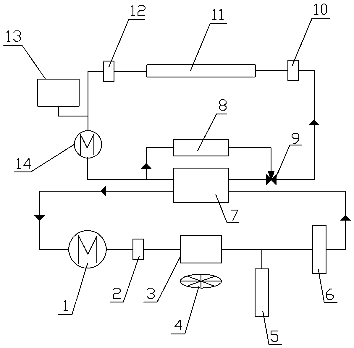
[0039] Such as Figure 1 to Figure 4 As shown, a power battery water-cooling unit system, the water-cooling unit and the water-cooling unit controller, the water-cooling unit includes a compressor 1, a pressure switch 2, a condenser 3, a condensation fan 4, a liquid storage drying tank 5, and an expansion valve 6. Plate exchanger 7, PTC heater 8, three-way valve 9, water inlet temperature sensor 10, power battery box 11, water outlet temperature sensor 12, water tank 13, electronic water pump 14, the compressor 1, pressure switch 2 , condenser 3, condensing fan 4, liquid storage drying tank 5, expansion valve 6, and plate exchanger 7 are connected in series; the PTC heater 8, three-way valve 9, water inlet temperature sensor 10, power battery box 11 , the water outlet temperature sensor 12, the water tank 13, and the electronic wate...


PUM


Abstract

The invention discloses a power battery water-cooling unit system and an intelligent temperature difference control method thereof. The power battery water-cooling unit system comprises a water cooling unit and a water cooling unit controller, wherein the water cooling unit comprises a compressor, a pressure switch, a condenser, a condensation fan, a liquid storing and drying tank, an expansion valve, a plate type exchanger, a PTC heater, a three-way valve, an inlet water temperature sensor, a power battery box, an outlet water temperature sensor, a water tank and an electronic water pump, wherein the compressor, the pressure switch, the condenser, the condensation fan, the liquid storing and drying tank, the expansion valve and the plate type exchanger are connected with each other in series. Through the power battery water-cooling unit system, the automation degree of the control of the power battery water-cooling unit is improved; the control system is capable of judging the difference between the battery average temperature and the outlet water temperature of the water cooling unit, adaptively adjusting operation rotation rate of the compressor, the electronic water pump and the condensation fan in real time through an intelligent control algorithm, indirectly controlling a battery to operate in the optimal temperature range and the optimal temperature difference range and predicting the battery temperature trend in advance through ampere-hour integral.

Description

technical field [0001] The invention relates to the application field of new energy vehicle power battery technology, more specifically, a power battery water-cooling unit system and its temperature difference intelligent control method. Background technique [0002] During the driving process of electric vehicles, complex chemical reactions occur in the power battery during charging and discharging, and it is easy to accumulate a large amount of heat inside the battery, resulting in a rise in battery temperature, resulting in a decline in battery performance indicators such as conversion efficiency and cycle life, while traditional power batteries are cooled. The system adopts natural air cooling and water cooling, and the high-power power battery adopts water cooling scheme. [0003] In the control of traditional power battery water-cooled units, the switch method is generally used to control, and the set temperature is compared with the battery temperature. Speed ​​opera...

Claims


Application Information

Patent Timeline
Patent Type & Authority Patents(China)
IPC IPC(8): H01M10/613H01M10/617H01M10/625H01M10/6567F25B49/02
CPCF25B49/02H01M10/613H01M10/617H01M10/625H01M10/6567Y02E60/10
Inventor 杨福清徐一凡宋光吉洪少阳陈伟李理林浩群
Owner XIAMEN KING LONG UNITED AUTOMOTIVE IND CO LTD
Why Eureka
Try Eureka