Electrical machine with an auxiliary movable self-directing stator

A stator and rotor technology, applied in the direction of synchronous machines, electrical components, electromechanical devices, etc., can solve problems such as reduced efficiency, limited operating range, rotor deformation, etc., to achieve the effect of reducing loss and avoiding hysteresis

Pending Publication Date: 2021-02-19
亚历山大伊斯克雷诺夫赫里斯托夫 +2
View PDF0 Cites 0 Cited by
  • Summary
  • Abstract
  • Description
  • Claims
  • Application Information

AI Technical Summary

Problems solved by technology

This increases the motor cost price as it complicates rotor manufacturing
The current produced depends on the rate of change of the magnitude of the magnetic field - increasing the rotational speed leads to increased losses and overheating, which limits the operating range, i.e. the maximum allowable rotational speed of the machine
Due to these losses, efficiency decreases with increasing machine angular velocity
Heat generation leads to deformation of the rotor and this further deteriorates the machine parameters
In the case of motors with an air-core non-magnetic armature, field dissipation severely degrades the characteristics of the motor and such motors are used only when fast response times are required

Method used


Image

  • Electrical machine with an auxiliary movable self-directing stator
  • Electrical machine with an auxiliary movable self-directing stator
  • Electrical machine with an auxiliary movable self-directing stator

Examples


Embodiment Construction

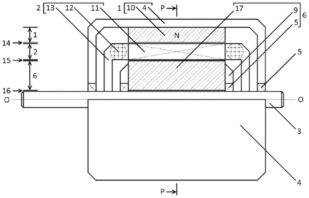
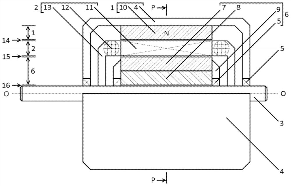
[0073] The invention is applicable to all types of electrical machines operating in generator or motor mode. For example, DC motor, induction motor, etc. While the invention is applicable to various types of electric motors and generators, the drawings consider brushed DC motors and induction motors in order to explain the same concepts for all electric motors. The drawings do not cover / exhaust all possible configurations.

[0074] figure 1 and figure 2 A simplified longitudinal top view of a brushed DC motor is shown. Only the stator and rotor designs are shown. The commutators are not shown in the figures as they are not directly relevant to the invention. Permanent magnets 10 securing the stator 1 are attached to the motor housing 4 (fasteners not shown). Bearing 5 allows free rotation of shaft 3 about the O-O axis. The hollow rotor 2 is attached to the shaft 3 by fasteners 13 and rotates together with the shaft 3 . A movable stator 6 is provided inside the rotor 2...


PUM


Abstract

An electrical machine with two or more stators is proposed. One stator (1) is stationary and is fixed to the body (4) of the machine, and the second stator (6) is movable and can rotate freely to boththe rotor (2) and the stationary stator (1). The movable stator (6) is self-orienting according to the lines of the magnetic field created by the electric windings and / or permanent magnets of the stationary stator (1). The movable stator (6) concentrates and shapes up the magnetic field B so that the magnetic lines are almost perpendicular to the rotor windings. The movable stator (6) does not rotate relative to the magnetic field of the stationary stator (1) and the magnetic field in it does not change, there is no continuous re-magnetization, magnetic hysteresis is avoided and no eddy currents are generated, due to which the losses and heating of the machine are reduced. The movable stator (6) may comprise permanent magnets to increase the magnetic field in the rotor active zones (2).

Description

technical field [0001] The present invention generally relates to electrical machines designed to convert mechanical energy to electrical energy and vice versa by using electromagnetic induction. More specifically, the invention relates to a method of directing a magnetic field by adding an auxiliary self-directing element called a movable stator to the stator and rotor of a machine. Background technique [0002] Each rotating electric machine has a stator and a rotor separated by a gap. The main part of an electric machine produced in motor mode at the time this patent application was filed uses a magnetic field to transfer energy between a stator and a rotor and transform electrical energy into mechanical motion. In generator mode, inverse commutation occurs - the magnetic field creates a current in the windings. In all electric machines, the direction of energy conversion can be changed, i.e. they can convert mechanical energy into electrical energy (generator mode) or ...

Claims


Application Information

Patent Timeline
Patent Type & Authority Applications(China)
IPC IPC(8): H02K16/02H02K21/02
CPCH02K16/02H02K21/029H02K16/04
Inventor 亚历山大·伊斯克雷诺夫·赫里斯托夫格奥尔基·伊斯克雷诺夫·赫里斯托夫普拉门·伊斯克雷诺夫·赫里斯托夫
Owner 亚历山大伊斯克雷诺夫赫里斯托夫
Why Eureka
Try Eureka