A permanent magnetic levitation device for linear motion

A linear motion and magnetic levitation technology, applied in the field of magnetic levitation, can solve problems such as inability to guarantee levitation, and achieve the effects of compact structure, simplified structure and convenient installation.

Active Publication Date: 2016-10-05
江苏金陵永磁产业研究院有限公司
View PDF5 Cites 0 Cited by
  • Summary
  • Abstract
  • Description
  • Claims
  • Application Information

AI Technical Summary

Problems solved by technology

This method cannot guarantee suspension at low speeds, and requires mechanical devices to achieve effective support

Method used


Image

  • A permanent magnetic levitation device for linear motion
  • A permanent magnetic levitation device for linear motion
  • A permanent magnetic levitation device for linear motion

Examples


Embodiment 1

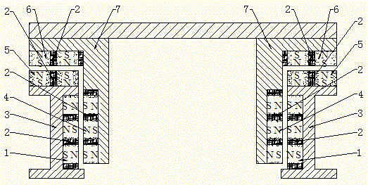
[0028] Such as figure 1 As shown, a permanent magnet magnetic levitation device for linear motion includes a track 3 and a bearing assembly 7. Two sets of suspended and fixed permanent magnet arrays 1 are respectively fixed in the grooves inside the "I"-shaped steel track 3, and the two sets of suspended The movable permanent magnet array 4 is fixed on the vertical end surfaces on both sides of the bearing assembly 7 and corresponds to a set of floating fixed permanent magnet arrays 1 respectively; On the upper plane, two groups of guided movable permanent magnet arrays 6 are fixed on the horizontal end surfaces on both sides of the carrier assembly 7 and are respectively parallel to a group of guided fixed permanent magnet arrays 5 directly below the guided movable permanent magnet arrays 6 . At this time, the oppositely arranged guide fixed permanent magnet array 5 and the guide movable permanent magnet array 6 are located on the upper side of the oppositely arranged suspend...

Embodiment 2

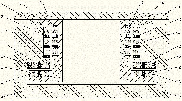
[0031] Such as figure 2 As shown, the difference from Embodiment 1 is that the present embodiment locates the opposite fixed permanent magnet array 5 and the movable permanent magnet array 6 at the position of the suspended fixed permanent magnet array 1 and the movable permanent magnet array 4 that are oppositely arranged. The lower side makes the guided movable permanent magnet array 6 of the carrying assembly 7 placed below the track guided fixed permanent magnet array 5, so that the vertical direction between the track guided fixed permanent magnet array 5 and the guided movable permanent magnet array 6 can be made The attractive force can counteract a part of the gravity of the bearing assembly 7 and enable the bearing assembly 7 to bear a greater load.

Embodiment 3

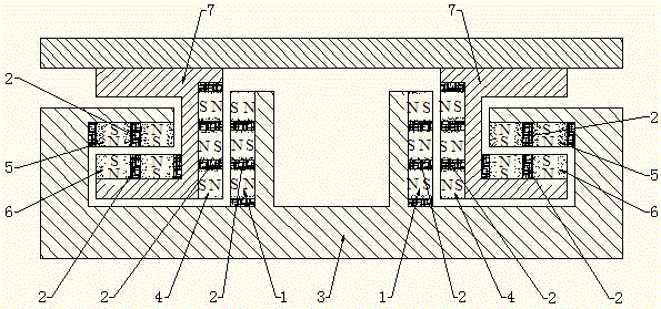
[0033] Such as image 3 As shown, the suspended movable permanent magnet array 4 and the guided movable permanent magnet array 6 on the carrier assembly 7 are arranged at the same horizontal position, and the suspended fixed permanent magnet array 1 and the guided fixed permanent magnet array 5 on the track 3 are also arranged at the same horizontal position. At the same horizontal position, compared with Embodiment 1 and Embodiment 2, the installation space of the device in the vertical direction is reduced, making the structure more compact.


PUM


Abstract

The invention discloses a permanent-magnet magnetic levitation device for linear motion. The permanent-magnet magnetic levitation device comprises a levitation fixed permanent-magnet array (1) and a levitation movable permanent-magnet array (4), as well as a guiding fixed permanent-magnet array (5) and a guiding movable permanent-magnet array (6) arranged oppositely; the levitation fixed permanent-magnet array (1) and the levitation movable permanent-magnet array (4) are arranged to provide a levitation adjusting force in the vertical direction in such a manner of same polarity at the same layer on the same side, opposite polarities of adjacent layers on the same side, and opposite polarities of the permanent magnets arranged oppositely at the same horizontal position; the guiding fixed permanent-magnet array (5) and the guiding movable permanent-magnet array (6) are arranged to provide a guiding adjusting force in the horizontal direction in such a manner of same polarity at the same layer on the same side, opposite polarities of adjacent rows on the same side, and opposite polarities of the permanent magnets arranged oppositely at the same vertical position. The permanent-magnet magnetic levitation device for linear motion is capable of generating great and relatively stable levitation adjusting force and guiding adjusting force, and is compact in structure, low in cost, convenient to mount, and suitable for popularization and utilization.

Description

technical field [0001] The invention relates to the technical field of magnetic levitation, in particular to a permanent magnet for linear motion which utilizes the properties of the permanent magnet magnetic field lines to have longitudinal anti-stretch force and transverse anti-compression force so that the levitation force and guiding force are perpendicular to the air gap magnetic force lines Magnetic levitation device. Background technique [0002] Traditional linear motion support methods mainly include rolling support and sliding support. These two support methods have mechanical contact, which will cause problems such as noise and heat generation. During long-term operation, wear and tear will occur, which will affect the service life of the device. Magnetic levitation support solves the above problems very well, eliminates the mechanical contact between the track and the bearing components, has no friction loss, and has lower energy consumption. It is an ideal suppo...

Claims


Application Information

Patent Timeline
Patent Type & Authority Patents(China)
IPC IPC(8): B60L13/04
Inventor 王向东
Owner 江苏金陵永磁产业研究院有限公司
Why Eureka
Try Eureka