Vehicle control system for aligning inductive charging connection

A technology of vehicle control system and inductive charging, which is applied in the direction of control/regulation system, vehicle position/route/height control, non-electric variable control, etc., and can solve difficult and time-consuming problems

Active Publication Date: 2015-08-19
FORD GLOBAL TECH LLC
View PDF5 Cites 16 Cited by
  • Summary
  • Abstract
  • Description
  • Claims
  • Application Information

AI Technical Summary

Problems solved by technology

However, this is a time-consuming task for the driver, and it is difficult for the d...

Method used


Image

  • Vehicle control system for aligning inductive charging connection
  • Vehicle control system for aligning inductive charging connection
  • Vehicle control system for aligning inductive charging connection

Examples


Embodiment Construction

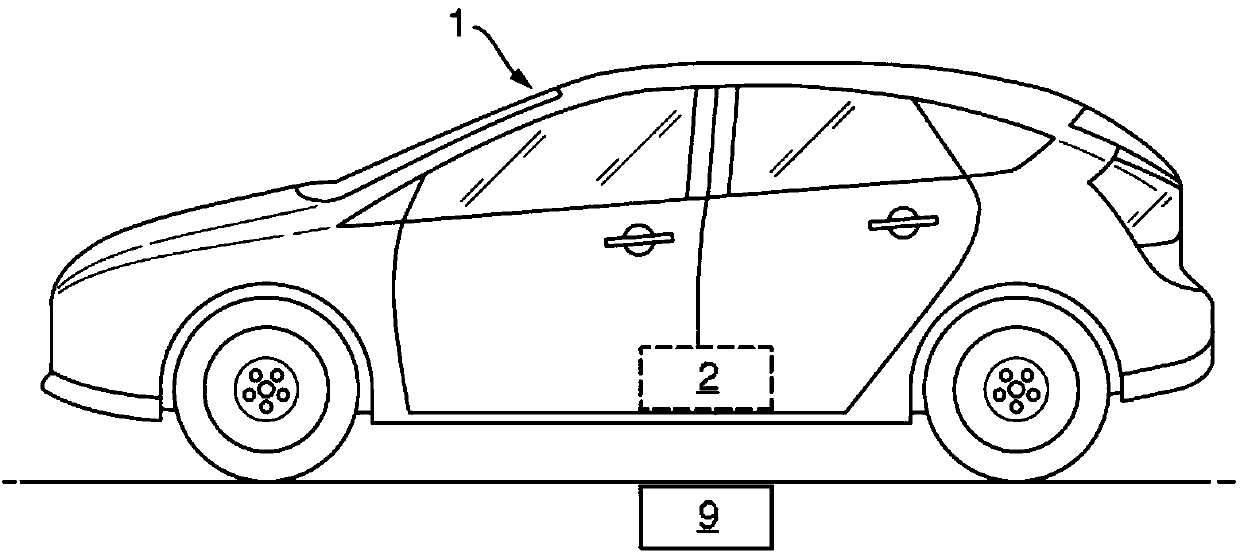
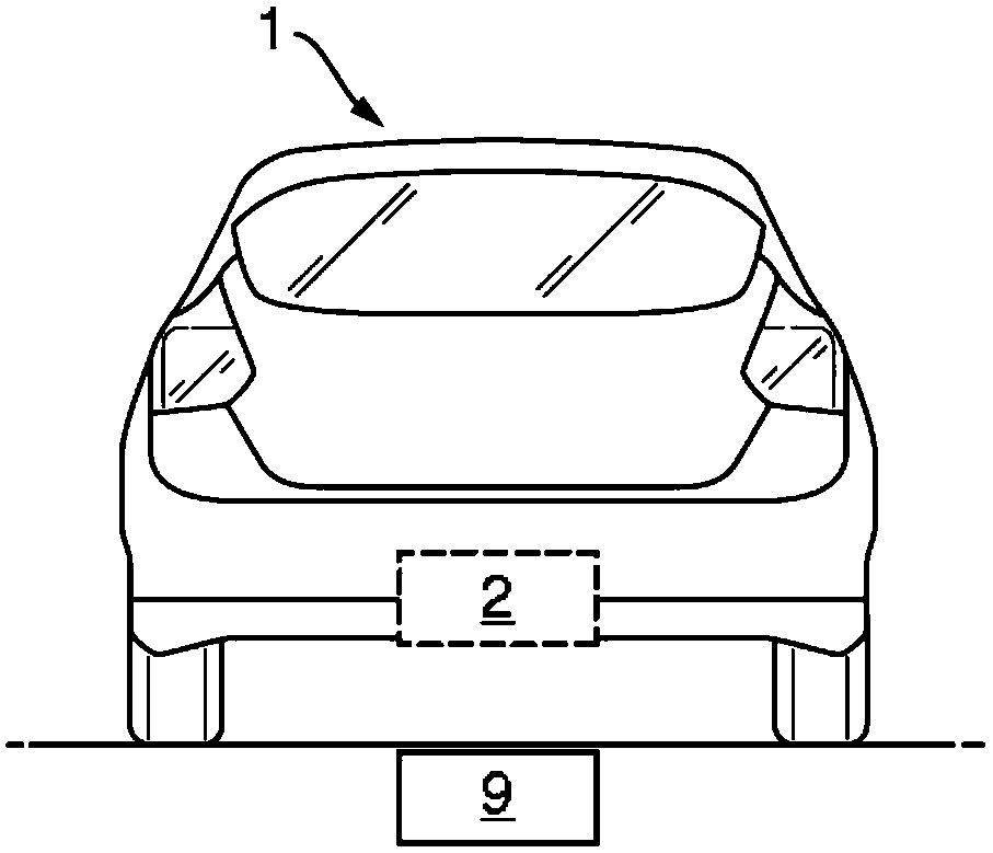
[0060] FIG. 1 shows a schematic diagram of a fixed inductive charging point 9 (FICP) located below a surface where a vehicle 1 can be positioned, and at least one mobile inductive charging point 2 (MICP) located on the underside of the vehicle 1 . In the figures, the mobile inductive charging point 2 and the fixed inductive charging point 9 are substantially aligned so that power can flow between the two inductive charging points 2 , 9 . Figure 1A The position of the inductive charging points 2 , 9 relative to the sides of the vehicle 1 is shown, Figure 1B The position of the inductive charging points 2 , 9 relative to the rear of the vehicle 1 is shown. Such as Figure 1A and 1B As shown, in a substantially aligned position, the inductive charging points 2 , 9 are aligned in a horizontal plane, so that the mobile inductive charging point 2 is positioned directly above the stationary inductive charging point 9 .

[0061] as Figure 1A and 1B Alternatively to the configurat...


PUM


Abstract

A vehicle control system, a surface marking for a surface upon which a vehicle can be positioned and a method of positioning a vehicle is provided. The vehicle control system is configured to position a vehicle. The vehicle comprises a mobile inductive charging point. The vehicle control system comprises one or more parking sensors configured to determine the position of the vehicle relative to a surface upon which the vehicle is positioned and/or obstacles around the vehicle. The one or more parking sensors are further configured to locate a visual indicator indicating the position of a fixed inductive charging point relative to the vehicle, and a parking assistance controller configured to automatically park the vehicle in a parking space on the surface based on data from the one or more parking sensors.

Description

[0001] The invention relates to a vehicle control system, in particular a control system for a vehicle with a mobile inductive charging point. The vehicle control system is configured to control the vehicle so that the mobile inductive charging point is automatically aligned with the fixed inductive charging point, the fixed inductive charging point being located at a fixed location relative to the mobile inductive charging point. The alignment of the fixed and mobile inductive charging points ensures that an inductive charge flow can be easily established between the fixed and mobile inductive charging points. Background technique [0002] It is known to use vehicle control systems to assist the driver in certain aspects of driving. For example, cruise control systems function to automatically maintain the speed of the vehicle at the speed set by the driver. Additionally, a parking assist system may assist the driver when parking the vehicle (eg, by controlling the direction...

Claims


Application Information

Patent Timeline
IPC IPC(8): B60W30/06B60W50/08
CPCE01F9/005B62D15/0285B60L11/1833B60L11/1835B60L11/1829B60W30/06B60W50/08G05D1/0225G05D1/0234G05D2201/0213B60L1/14B60L2250/10B60L2250/16Y02T10/7072Y02T90/14Y04S30/14B60L53/37B60L53/65B60L53/124B60L53/126B60L53/305Y02T10/70Y02T90/12Y02T90/167Y02T90/16B60L53/12B62D15/027B62D15/028B60L53/36B60L53/38
Inventor 多纳图斯·安德里亚斯·约瑟芬·吉斯塞米·菲利蒙·彼得里迪斯
Owner FORD GLOBAL TECH LLC
Why Eureka
Try Eureka