
A feeding auger

An auger and feeding technology, which is applied in the field of auger with slow feeding, can solve the problem that conveying and drying cannot be taken into account at the same time.

Active Publication Date: 2017-02-01
SNF CHINA FLOCCULANT
View PDF4 Cites 0 Cited by
  • Summary
  • Abstract
  • Description
  • Claims
  • Application Information

AI Technical Summary

Problems solved by technology

[0003] Aiming at the deficiency that conveying and drying cannot be taken into account at the same time in the prior art, the present invention provides a feeding auger with a compact structure that can take care of both material conveying and drying

Method used


Image

  • A feeding auger

Examples


Embodiment Construction

[0010] The present invention will be further described below in conjunction with drawings and embodiments.

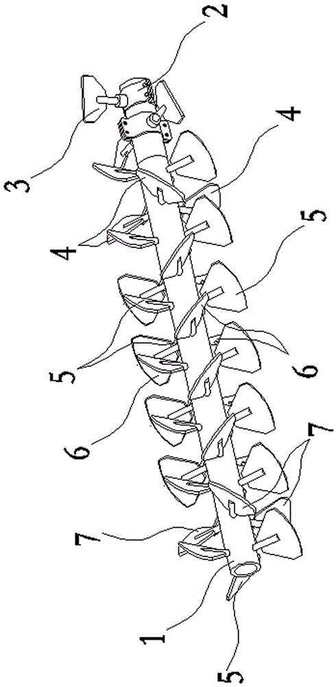
[0011] figure 1 As shown: a feeding auger includes a rotating shaft 1 , a feeding connecting sleeve 2 , a feeding connecting sleeve blade 3 , a feeding blade 4 , a propulsion blade 5 , a retarding blade 6 and a discharging blade 7 . The feeding end of the rotating shaft 1 is connected to the power motor through two feeding connecting sleeves 2, and the outer circumference of the feeding connecting sleeve 2 is evenly distributed with more than two feeding connecting sleeve blades 3 inclined toward the advancing direction of the auger, adjacent to each other. The blades 3 of the feed connection sleeve on the feed connection sleeve 2 are staggered. In the direction of rotation and propulsion of the rotating shaft 1, multiple sets of propulsion blade groups, more than one set of feed blade groups, more than one set of slow blade groups, and more than one set of discharge b...


PUM


Abstract

The invention relates to a feeding auger which comprises a rotating shaft and a blade group. The blade group comprises multiple propelling blade groups, a feeding blade group, multiple slowing blade groups and a discharging blade group, wherein the multiple propelling blade groups are evenly distributed on a rotating shaft in the axial direction of the rotating shaft, the feeding blade group is arranged between the first propelling blade group and the second propelling blade group of the multiple propelling blade groups and comprises three feeding blades, the three feeding blades are staggered by 60 degrees, corresponding to three propelling blades, along the circumference of the rotating shaft or along outer circle spiral line in the propelling direction of auger and arranged on the rotating shaft. The discharging blade group is arranged between the last one propelling blade group and the last but one propelling blade group of the multiple propelling blade groups, the multiple slowing blade groups are arranged between the feeding blade group and the discharging blade group and are arranged among the multiple propelling blade groups at intervals, each slowing blade group comprises three slowing blades, and the slowing blades are staggered by 90 degrees, corresponding to three propelling blades, along the circumference of the rotating shaft or along outer circle spiral line in the propelling direction of auger and arranged on the rotating shaft.

Description

technical field [0001] The invention relates to an auger, in particular to an auger for slow feeding. Background technique [0002] The auger includes a rotating shaft and a helical blade. The helical blade is driven by the rotating shaft to propel the material. It is generally used for direct conveying of granular or powdery materials. Most of the traditional augers have a one-way conveying structure. In some special occasions, For example, when conveying and drying are required to be carried out at the same time, due to the high speed of material conveying, the drying effect of the material is poor, which cannot meet the requirements of conveying and drying. Contents of the invention [0003] Aiming at the deficiency in the prior art that conveying and drying cannot be taken into account at the same time, the present invention provides a feeding auger with a compact structure that can take care of both conveying and drying of materials. [0004] The technical solution a...

Claims


Application Information

Patent Timeline
Patent Type & Authority Patents(China)
IPC IPC(8): B65G33/26
CPCB65G33/26B65G2812/0527
Inventor 高军任聪
Owner SNF CHINA FLOCCULANT
Learn More