Magnetic pressure type reading stand
A technology for reading racks and magnets, applied in the field of reading racks, can solve problems such as difficulty in adapting to magnetic suction and clamping of books and periodicals
- Summary
- Abstract
- Description
- Claims
- Application Information
AI Technical Summary
Problems solved by technology
Method used
Image
Examples
no. 1 approach
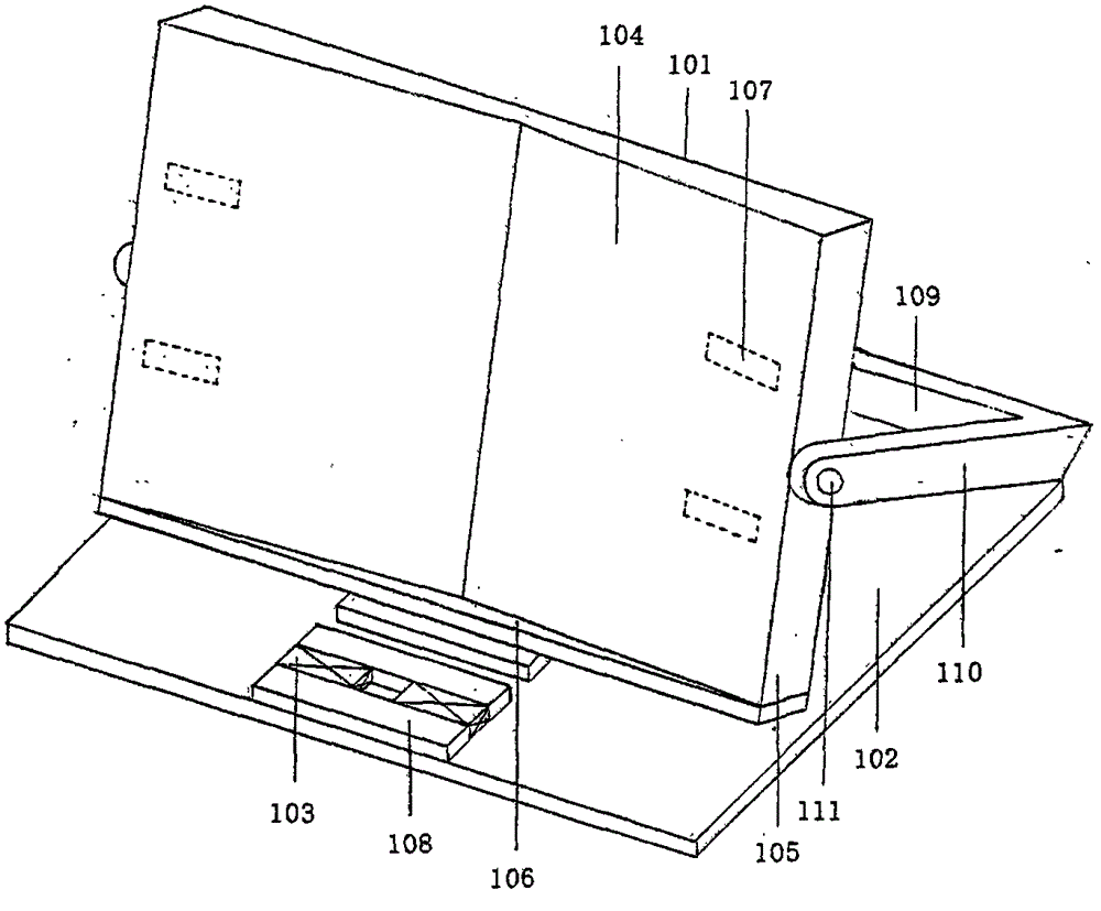
[0017] figure 1 It is the first embodiment of the magnetic pressure type reading frame: in the following embodiments, the movable connection joint between the longer sides of each board is defined, which can be a shaft connection or a hinge connection. Sealing plate and thin iron sheet are not shown among the figure.
[0018] Such as figure 1 As shown, this embodiment is similar to CN201320229088.0, and in the current technology, it includes a top plate 101 , a bottom plate 102 and a strip magnet 103 . The top plate 101 is covered with a load-bearing plate 104 with an obtuse angle. The angle of the obtuse angle is preferably between 160 and 170 degrees. The upper part of the cavity is sealed by two triangular sealing plates, and the lower part is sealed by a strip-shaped supporting plate 106. The supporting plate 106 is exposed on the vertical triangular plate surface of the bearing plate, just supporting the In this way, when the books and periodicals are laid out flat, ...
no. 2 approach
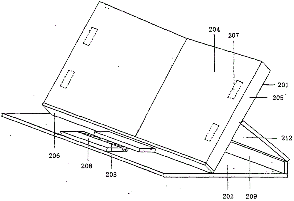
[0026] Such as figure 2 In the shown second embodiment, the top plate 201 is slightly smaller than the bottom plate 202, the longer edge of the bottom plate 202 is fixed or movably connected to a supporting side plate 209, and the middle part of the back plate of the top plate 201 is horizontally and movably connected to a support plate 212, The edge of the other side of the support plate 212 is fixedly connected with the support side plate 209 or is movably connected with each other.
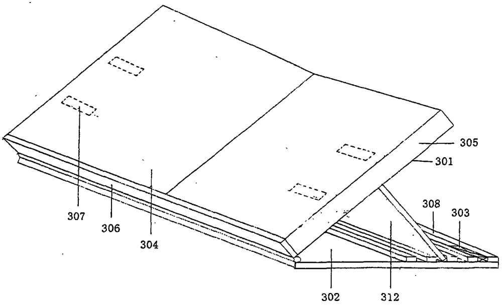
[0027] As in Embodiment 1, when the magnetic pressure type reading rack is stored, the front surface 204 of the bearing plate of the magnetic clamping device is reversed on the bottom plate 202, and a hollow triangular cavity is formed between the reversed bearing plate 204 and the bottom plate 202. Side-by-side shorter ledges 208 can be accommodated. When unfolding, the magnetic suction clamping device is flipped back and forth to the bottom of the side with the supporting plate 206, and the...
no. 4 approach
[0032] Such as Figure 4 In the fourth embodiment shown, the length and width of the bottom plate 402 and the top plate 401 are the same, the middle part of the back plate of the top plate 401 is horizontally connected to a support plate 412, and the other edge of the support plate 412 is movably connected with the longer edge of the bottom plate 402. The other side of the bottom plate 402 is provided with a longer convex ridge 408 .
[0033] When the magnetic pressure reading rack is stored, the support plate 412 is attached to the back plate of the top plate 401 in the opposite direction of the supporting plate 406, and the front of the carrying plate 404 is placed flat on the magnetic clamping device. When unfolded, the magnetic clamping device is tilted The upper part is lifted up and erected obliquely, and the edge of the top plate 401 and the back plate at the bottom are obliquely connected to the edge of any longer convex ridge 408 to obtain the required reading support a...
PUM
 Abstract
Description
Claims
Application Information
 - R&D
- Intellectual Property
- Life Sciences
- Materials
- Tech Scout
- Unparalleled Data Quality
- Higher Quality Content
- 60% Fewer Hallucinations
Browse by: Latest US Patents, China's latest patents, Technical Efficacy Thesaurus, Application Domain, Technology Topic, Popular Technical Reports.
© 2025 PatSnap. All rights reserved.Legal|Privacy policy|Modern Slavery Act Transparency Statement|Sitemap|About US| Contact US: help@patsnap.com


