
Drainage tube

A technology of drainage tube and drainage port, which is applied in the direction of balloon-shaped catheter, etc., can solve the problems of increasing the chance of infection, increasing the workload of nursing staff and the difficulty of nursing, insufficient drainage can not achieve the therapeutic effect, etc., and achieve the effect of convenient insertion operation

Inactive Publication Date: 2015-08-26
徐增良
View PDF11 Cites 1 Cited by
  • Summary
  • Abstract
  • Description
  • Claims
  • Application Information

AI Technical Summary

Problems solved by technology

[0002] Intraventricular hemorrhage or cerebral parenchymal hemorrhage breaks into the ventricle, and external ventricular drainage is often required. The currently used ventricular drainage tube is a long columnar end with a side hole. The end of this type of drainage tube is smooth. The ventricles will gradually shrink. With the shrinking of the ventricles, or under the premise of pulling the drainage tube externally, the end of the ventricle drainage tube will often protrude from the ventricular system, resulting in drainage failure
In addition, ordinary ventricular drainage tubes have no pressure control capability, and the pressure control is determined by the height of the external drainage bottle suspension. Because the change of the patient's head position will directly lead to excessive drainage or insufficient drainage, insufficient drainage will not achieve the desired therapeutic effect , Excessive drainage will cause excessive reduction of intracranial pressure and cause or aggravate cerebral hemorrhage. Nurses must constantly observe the height of the hanging drainage bottle, and adjust the height of the drainage bottle in time according to the position of the patient's head. The purpose of treatment has been achieved. Significantly increased the workload of nursing staff and the difficulty of nursing; the ordinary ventricular drainage tube has no valve to control the flow direction, and the cerebrospinal fluid that has flowed out of the ventricular drainage tube from the ventricular drainage tube will flow back due to the change of the pressure in the ventricle or the change of the position of the external drainage bottle. Increase the chance of infection in the back room

Method used


Image

  • Drainage tube
  • Drainage tube
  • Drainage tube

Examples


Embodiment Construction

[0027] The present invention is described below based on examples, but the present invention is not limited to these examples. In the following detailed description of the invention, some specific details are set forth in detail. The present invention can be fully understood by those skilled in the art without the description of these detailed parts. In order to avoid obscuring the essence of the present invention, known structures and methods are not described in detail.

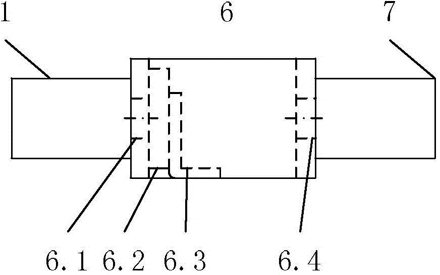
[0028] Drainage tube in the present embodiment, see Figure 1-2 As shown, it includes an expandable elastic capsule 3, a catheter 2, and a drainage tube main body 1. The elastic capsule 3 has a hollow cavity, and the ventricle end 5 of the drainage tube main body has a closed end, and a drainage port 4 is provided near the closed end. The elastic capsule 3 is fixedly arranged on the outer periphery of the main body of the drainage tube. The catheter communicates with the elastic capsule for injecting flui...


PUM


Abstract

The invention relates to a drainage tube. The drainage tube is used for solving the problem that drainage tubes are prone to falling off from a brain ventricle. The drainage tube comprises an expandable elastic bladder (3), a catheter (2) and a drainage tube body (1). The elastic bladder (3) is provided with a hollow cavity; the ventricle end (5) of the drainage tube body is a closed end, and a drainage port (4) is formed close to the closed end; the elastic bladder (3) is arranged on the circumference of the drainage tube; the catheter (2) is communicated with the elastic bladder (3) and used for filling fluid into the cavity to expand the elastic bladder (3); the elastic bladder is not communicated with the drainage tube body. According to the drainage tube, the expandable elastic bladder formed in the drainage tube can limit the drainage tube inside the brain ventricle to prevent the drainage tube from falling off from the ventricle, thereby effectively avoiding accidents during a drainage process.

Description

technical field [0001] The invention relates to a medical device, in particular to a drainage tube, in particular to a special anti-slip extraventricular drainage tube for neurosurgery. Background technique [0002] Intraventricular hemorrhage or cerebral parenchymal hemorrhage breaks into the ventricle, and external ventricular drainage is often required. The currently used ventricular drainage tube is a long columnar end with a side hole. The end of this type of drainage tube is smooth. The ventricle will gradually shrink. With the shrinkage of the ventricle, or under the premise of pulling the drainage tube with external force, the end of the ventricle drainage tube will often protrude from the ventricular system, resulting in drainage failure. In addition, ordinary ventricular drainage tubes have no pressure control capability, and the pressure control is determined by the height of the external drainage bottle suspension. Because the change of the patient's head positio...

Claims


Application Information

Patent Timeline
IPC IPC(8): A61M25/10
Inventor 徐增良张林涛棊淑杰綦玉洁
Owner 徐增良
Learn More