Method For Calibrating Laser Scanners To A Container Transportation Crane

A laser scanner, crane technology, used in cranes, trolley cranes, transportation and packaging, etc., can solve problems such as difficult measurement

Active Publication Date: 2015-08-26
SIEMENS AG +1
View PDF6 Cites 15 Cited by
  • Summary
  • Abstract
  • Description
  • Claims
  • Application Information

AI Technical Summary

Problems solved by technology

However, the positions of those datum structures on cranes or on the ground c

Method used


Image

  • Method For Calibrating Laser Scanners To A Container Transportation Crane
  • Method For Calibrating Laser Scanners To A Container Transportation Crane
  • Method For Calibrating Laser Scanners To A Container Transportation Crane

Examples


Embodiment Construction

[0026] In container transshipment terminals, elevated containers, especially so-called STS cranes, transfer containers from ships to land, either directly onto trucks or trains, or onto transport vehicles that are often designed as straddle vehicles.

[0027] On land, as well as in portless container depots, containers are transferred or loaded onto trucks or trains using stacking or gantry cranes, especially unmanned overhead stacking racks (ASC).

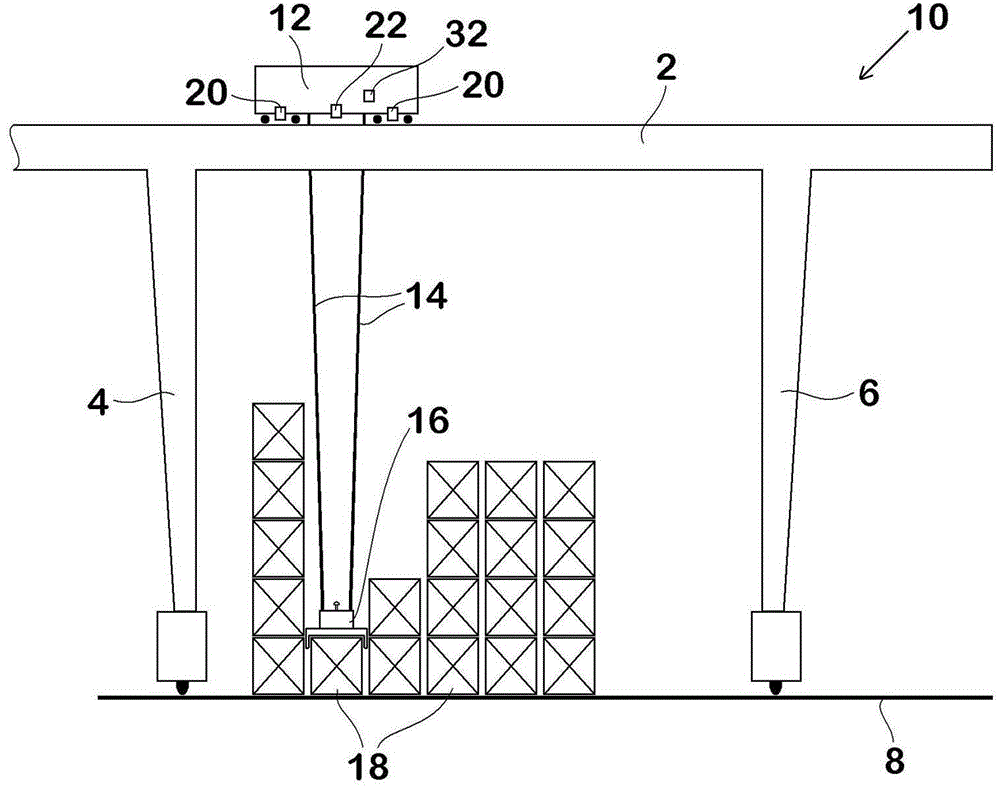
[0028] figure 1 An ASC crane 10 is shown, which has a horizontal crane gantry, which is carried by frames 4 , 6 , which run on the ground 8 on rails not shown. A trolley 12 runs along the crane frame 2 on which a hoisting mechanism 16 for ISO containers 18 , a so-called spreader, is suspended via steel cables 14 , so that the containers 18 are stacked and unstacked in the working area of ​​the crane 10 Stack or transfer stack. The container 18 can be taken off from or loaded onto a truck or train that can drive under the crane 1...


PUM


Abstract

The invention relates to a method for calibrating 3D laser scanners (20). The laser scanner is fixed on a support structure (12) of a crane used for container transportation, so that the containers (18) can be scanned in a working zone of the crane. The calibration includes at least one scanning of a calibrator (24) having ISO container features. The calibrator has a calibration mark (26) and can carry recognition and positioning during a scanning process. The method measures movement offset of at least one laser scanner relative to the support structure if the movement offset is not known. The crane is controlled, so that the calibrator can be caught and brought to different predetermined heights above the ground (8) and the scanning of the calibrator is performed through at least one laser scanner. The rotation offset of the at least one laser scanner (20) relative to the support structure (12) can be measured with the scanning result and the movement offset.

Description

technical field [0001] The invention relates to a method of calibrating a laser scanner according to the preamble of claim 1 . Background technique [0002] A method of this type is known from DE 10 2008 019 373 A1. Instead of the conventional method of placing a calibration body on the ground, manually measuring with respect to a crane and then scanning, a container is placed on the ground in the scanner detection area and then scanned. Since the normal dimensions of the container are not suitable for calibration, an additional compensation with respect to the measuring point and structure can be achieved either out of the crane or on the ground or on another object. In this way, disturbances in ongoing operations are reduced by calibration. However, the positions of those reference structures on cranes or on the ground cannot be readily obtained with the desired accuracy and are not easily measured. Contents of the invention [0003] The object of the present inventio...

Claims


Application Information

Patent Timeline
IPC IPC(8): B66C13/18B66C19/00
CPCB66C19/007B66C13/46
Inventor 拉尔斯·安布罗西迈克尔·本克梅利津·尼泽尔迈克尔·席科拉
Owner SIEMENS AG
Why Eureka
Try Eureka