Antenna calibration method and apparatus

A technology for antenna calibration and signal calibration, which is applied in the field of radio frequency transmission and can solve problems such as increasing the complexity of UE implementation

Active Publication Date: 2009-08-05
DATANG MOBILE COMM EQUIP CO LTD
View PDF0 Cites 16 Cited by
  • Summary
  • Abstract
  • Description
  • Claims
  • Application Information

AI Technical Summary

Problems solved by technology

[0009]In the existing antenna calibration method, the signaling support of the air interface is required, and the standard support is required, and the UE is used to assist in the calibration, and the UE needs to complete the parameters in the calibration Work such as measurement and sending measurement reports increases the complexity of UE implementation

Method used


Image

  • Antenna calibration method and apparatus
  • Antenna calibration method and apparatus
  • Antenna calibration method and apparatus

Examples


no. 1 example

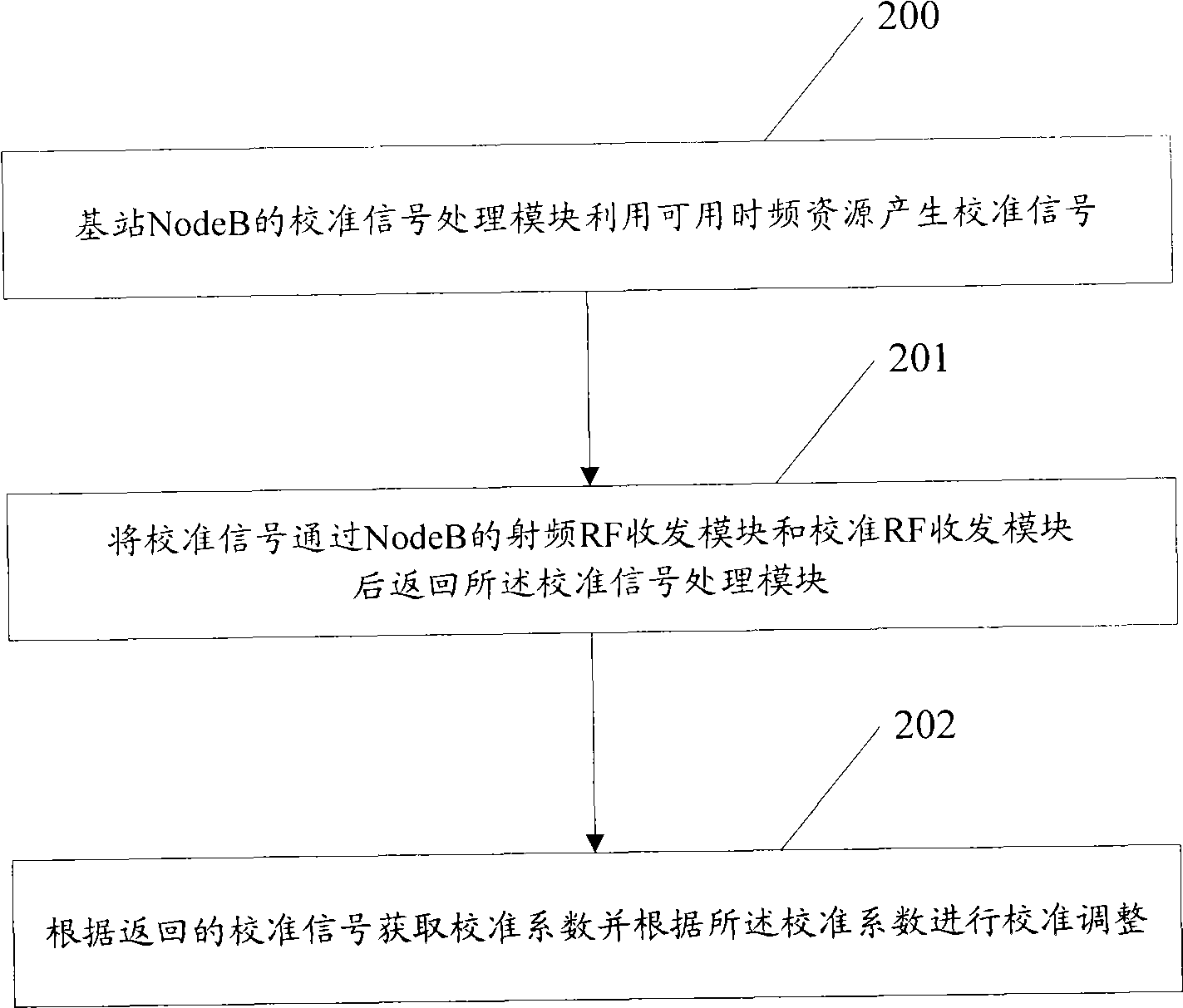
[0030] figure 2 The flow chart of the antenna calibration method provided by the embodiment of the present invention. Such as figure 2 Shown:

[0031] Step 200: The calibration signal processing module of the base station NodeB utilizes available time-frequency resources to generate a calibration signal.

[0032] Step 201: Return the calibration signal generated in step 200 to the calibration signal processing module after passing through the RF transceiver module of the NodeB and the calibration RF transceiver module.

[0033] This step can be specifically:

[0034] A. Send the calibration signal generated by the calibration signal processing module of NodeB to the RF transceiver module of NodeB, and the RF transceiver module of NodeB modulates the received calibration signal to the first frequency point, and couples the modulated calibration signal to the calibration RF transceiver module, the calibration RF transceiver module returns the calibration signal from the RF...

no. 2 example

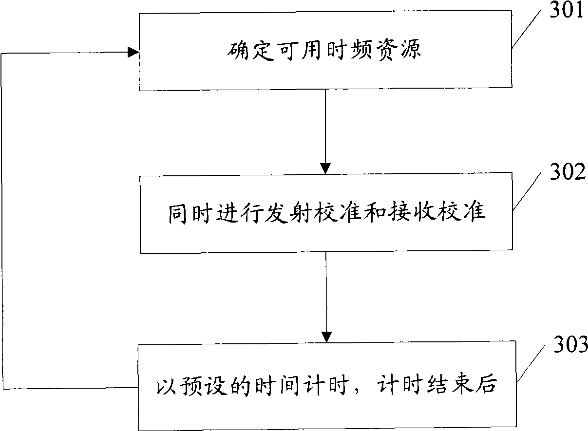
[0048] image 3 It is a flow chart of the antenna calibration method provided by the embodiment of the present invention. Such as image 3 Shown:

[0049] Step 301: Determine available time-frequency resources.

[0050] Wherein, the determination of available time-frequency resources may be implemented in the following manner:

[0051] Figure 4 It is a schematic diagram of time-frequency resources under the three implementation modes of step 301. In the figure, Calibration indicates that the specified time-frequency resources cannot be used to carry user data or control commands, and Idle indicates that time-frequency resources other than those specified for carrying user data or control commands are specified. , the remaining free time-frequency resources, Data / Control represents the time-frequency resources used to carry data or control commands, Subframe represents the subframe, DwPTS represents the downlink pilot channel, UpPTS represents the uplink pilot channel, PRB...

no. 3 example

[0081] Figure 7 The structure diagram of the antenna calibration device provided by the embodiment of the present invention. Such as Figure 7 Shown:

[0082] The antenna calibration device provided by the embodiment of the present invention includes: a calibration signal processing module 701 of NodeB, an RF transceiver module 702 and a calibration module 703 of NodeB.

[0083] The calibration signal processing module 701 of the NodeB is configured to use the calibration signal generated by the available time-frequency resources, receive the returned calibration signal, obtain the calibration coefficient according to the returned calibration signal, and perform calibration adjustment according to the calibration coefficient.

[0084] The calibration module 703 is configured to pass the calibration signal generated by the calibration signal processing module 701 of the NodeB through the RF transceiver module 702 of the NodeB and the calibration RF transceiver module 7032, a...


PUM


Abstract

The embodiment of the invention provides an antenna calibration method and a device thereof. The method comprises the steps as follows: a calibrating signal processing module of a base station NodeB utilizes usable time frequency resource to generate a calibrating signal; the calibrating signal passes through an RF (radio frequency) transceiver module and a calibration RF transceiver module of the NodeB and then is returned to the calibrating signal processing module; and calibration factors are obtained according to the returned calibrating signal and calibrating adjustment is carried out according to the calibration factors. The antenna calibration is realized by returning the calibrating signal sent by the NodeB to the NodeB and does not need UE assistance, and therefore the antenna calibration can be realized without the support of air interface signaling.

Description

technical field [0001] The invention relates to the technical field of radio frequency transmission, in particular to an antenna calibration method and device. Background technique [0002] In the traditional Time Division-Synchronous Code Division Multiple Access (TD-SCDMA, Time Division-Synchronous Code Division Multiple Access) system based on the Time Division Duplex (TDD, Time Division Duplex) mode, the antenna calibration technology has been successfully applied. The main purpose of antenna calibration is to make the radio frequency (RF) link electrical characteristics of each antenna in the NodeB antenna array consistent, and the electrical characteristics of each uplink / downlink radio frequency link are also consistent. Here, the antenna and its corresponding link are referred to as RF transceiver modules. It can be seen that the base station (NodeB) includes multiple RF transceiver modules. In addition, the NodeB also includes a calibration signal processing modul...

Claims


Application Information

Patent Timeline
Patent Type & Authority Applications(China)
IPC IPC(8): H04W16/28H04W24/00H04W88/08H01Q3/26
Inventor 侯云哲索士强肖国军孙韶辉
Owner DATANG MOBILE COMM EQUIP CO LTD
Why Eureka
Try Eureka