Method for automatically measuring and correcting welding gun gesture of welding robot

A welding robot and automatic measurement technology, applied in welding equipment, auxiliary welding equipment, welding/cutting auxiliary equipment, etc., can solve problems affecting welding or glue quality, track deviation, tool offset, etc., to improve welding movement The effect of trajectory accuracy, improved accuracy, and reduced calibration time

Active Publication Date: 2020-06-19
FUJIAN SPECIAL EQUIP TESTING RES INST
View PDF8 Cites 17 Cited by
  • Summary
  • Abstract
  • Description
  • Claims
  • Application Information

AI Technical Summary

Problems solved by technology

For example: in the process of arc welding, spot welding, assembly, and gluing, where the end tool of the welding robot will be in close contact with the workpiece, factors such as fixture wear and collision tilt will cause the tool's pose to change, causing the welder to , gluing machine and other end tools collide with the workpiece, and the TCP of the tool coordinate system of the welding robot deviates, causing the trajectory to deviate, which cannot meet the process requirements and seriously affects the quality of welding or gluing
Traditional welding robot torch measurement and calibration methods require manual participation, low efficiency, and accuracy is also affected by operator proficiency and human eye resolution

Method used


Image

  • Method for automatically measuring and correcting welding gun gesture of welding robot
  • Method for automatically measuring and correcting welding gun gesture of welding robot
  • Method for automatically measuring and correcting welding gun gesture of welding robot

Examples


Embodiment Construction

[0026] The present invention will be further described below in conjunction with the accompanying drawings.

[0027] see Figure 1 to Figure 6 , the present invention provides a method for automatically measuring and correcting the posture of a welding torch of a welding robot, which is realized according to the following steps:

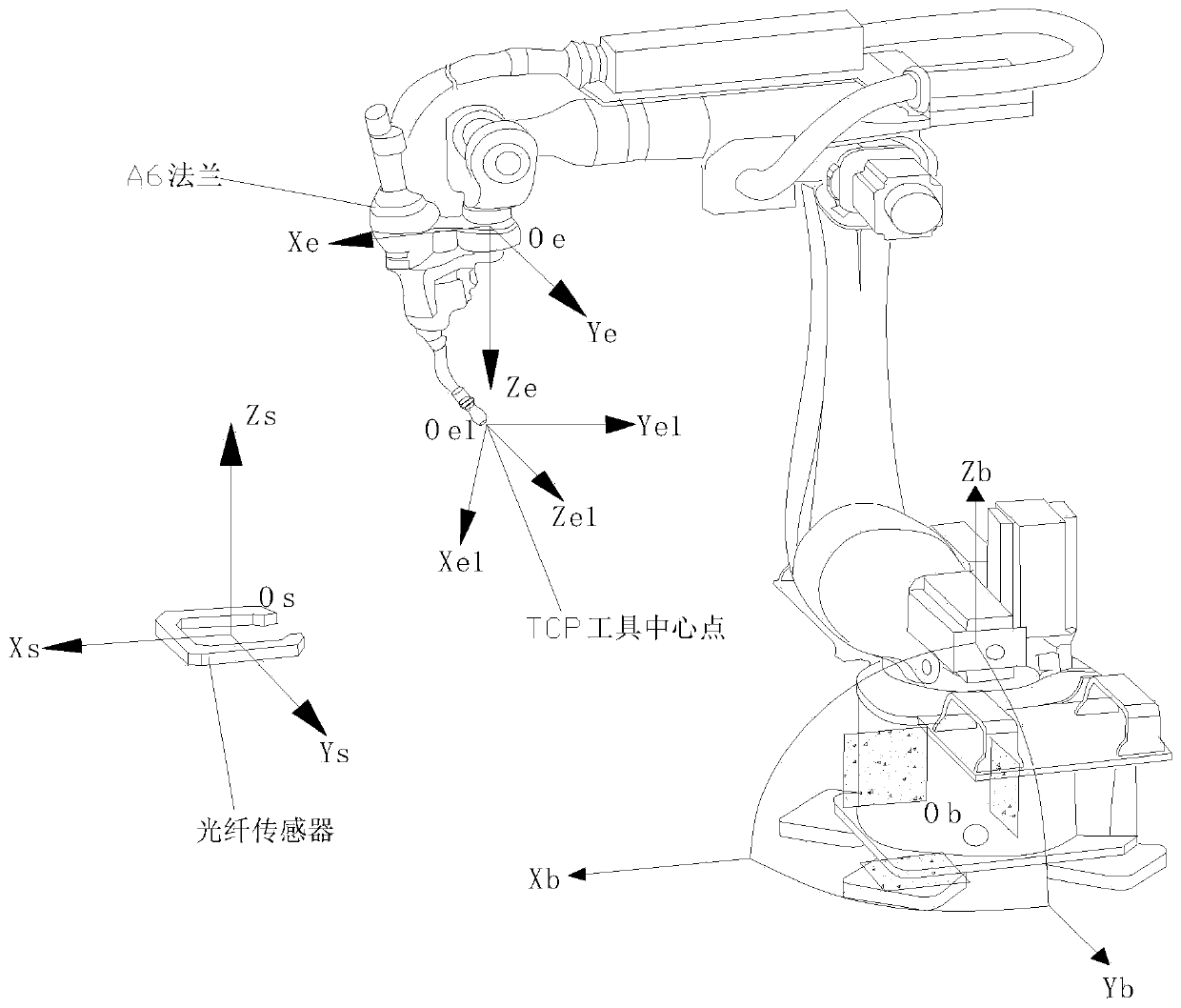
[0028] Step S1: Build a hardware environment, connect the welding robot with the first optical fiber sensor, the second optical fiber sensor, and the controller to ensure normal communication; install the first optical fiber sensor and the second optical fiber sensor on the same plane;

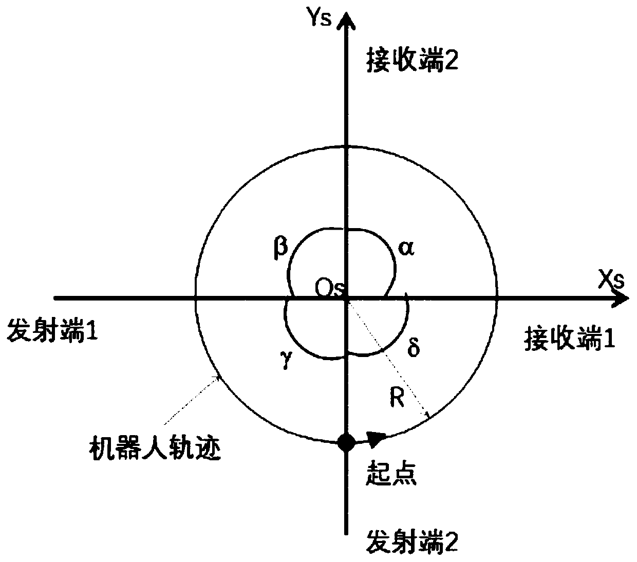
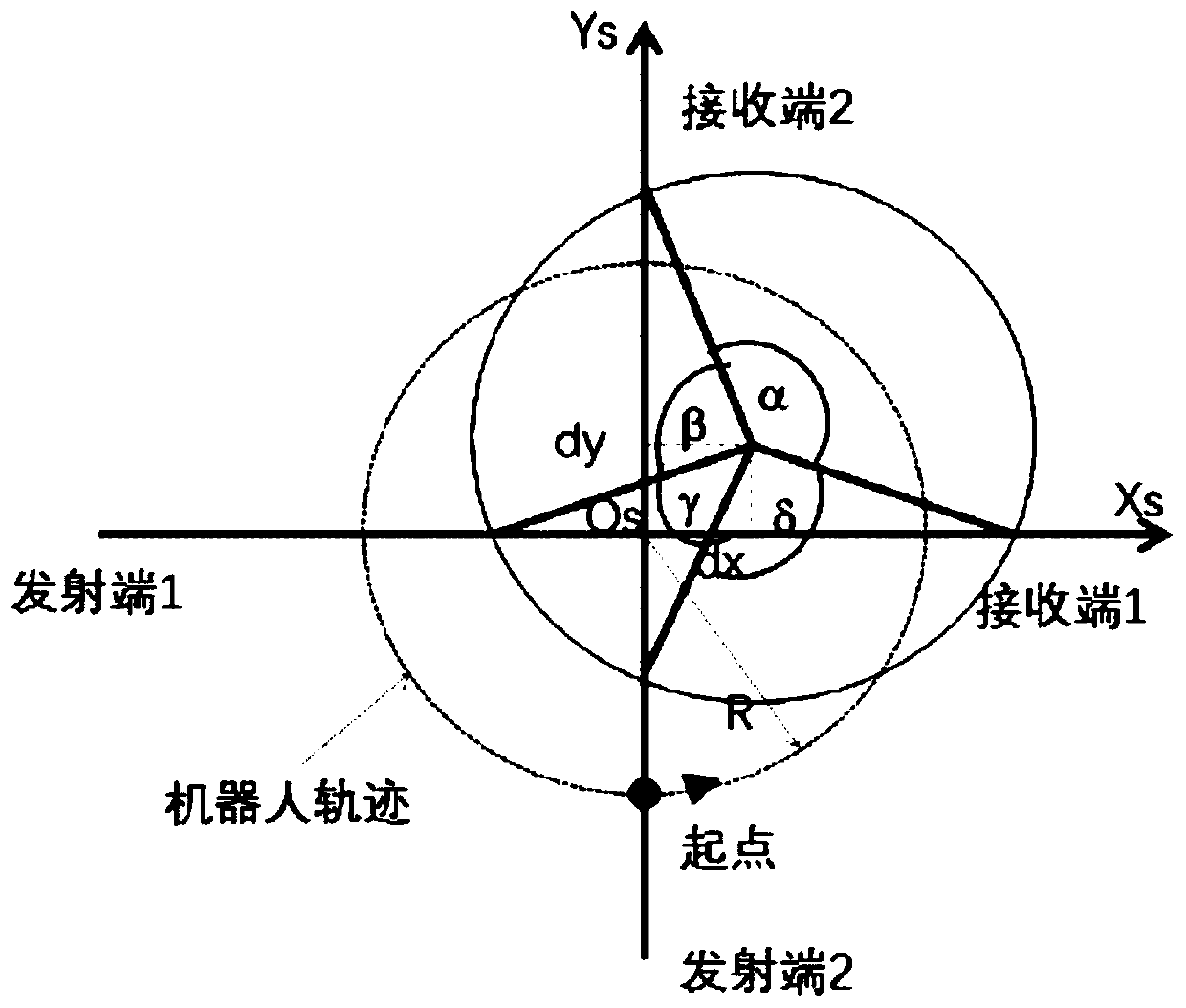
[0029] Step S2: establish a coordinate system, the sensor coordinate system O constructed with the ray intersection point of the first optical fiber sensor and the second optical fiber sensor as the origin S x S Y S Z S , X s Axis, Y s Axis, Z s The axis direction is consistent with the root coordinate system direction of the welding robot; the tool coordinate...


PUM


Abstract

The invention relates to a method for automatically measuring and correcting a welding gun gesture of a welding robot. The method comprises a welding robot and is realized according to the following steps of: S1: building a hardware environment; S2: establishing a coordinate system; S3: according to time recorded by a controller, calculating a trajectory circle center O1 coordinate (d<x1>, d<y1>);S4: according to the time recorded by the controller, calculating a trajectory circle center O2 coordinate (d<x2>, d<y2>; S5: using a spatial vector to calculate the gesture, compensating an originaltool TCP (Tool Center Point) gesture, and then, regulating the gesture of a tool; S6: enabling a welding robot TCP to carry out constant speed circular motion around the original point of the coordinate system of a sensor at the same angular speed by the same radium to obtain that Ox-Os is equal to (0, 0, 0); and S7: calculating an offset, and feeding back the offset to the inside of the weldingrobot to realize TCP automatic correction. A high-accuracy sensor is adopted to carry out non-contact measurement, so that the measurement and the calibration of a tool coordinate system can be accurately realized, calibration time is shortened, and the accuracy of a measurement result and the accuracy of a welding motion trajectory are improved.

Description

technical field [0001] The invention relates to the technical field of industrial welding robots, in particular to a method for automatically measuring and correcting the posture of a welding torch of a welding robot. Background technique [0002] In the modern industrial production process, when the welding robot tool coordinate system tool is working, it will inevitably collide with the workpiece, which will cause the welding robot tool coordinate system tool to shift. For example: in the process of arc welding, spot welding, assembly, and gluing, where the end tool of the welding robot will be in close contact with the workpiece, factors such as fixture wear and collision tilt will cause the tool's pose to change, causing the welder to , Gluing machine and other end tools collide with the workpiece, and the TCP of the tool coordinate system of the welding robot deviates, causing the trajectory to deviate, unable to meet the process requirements, and seriously affecting th...

Claims


Application Information

Patent Timeline
Patent Type & Authority Applications(China)
IPC IPC(8): B23K37/02B25J9/16B25J19/00
CPCB23K37/0252B25J9/1692B25J19/0095
Inventor 陈挺木曾远跃陈照春郑耿峰黄栋陈浩龙林景彩
Owner FUJIAN SPECIAL EQUIP TESTING RES INST
Why Eureka
Try Eureka