Supercharge Your Innovation With Domain-Expert AI Agents!

Dynamic Compensation Circuit

A technology for compensating signals and compensating units, which is applied in the direction of measuring electricity, measuring electrical variables, and voltage/current isolation, and can solve problems such as unavailability and measurement errors.

Active Publication Date: 2015-08-26
TEKTRONIX INC
View PDF6 Cites 4 Cited by
  • Summary
  • Abstract
  • Description
  • Claims
  • Application Information

AI Technical Summary

Problems solved by technology

Temperature, mechanical stress, and signals applied to the optical sensor can dynamically drift the sensor's DC / LF offset component, rendering it unusable or causing significant measurement errors

Method used


Image

  • Dynamic Compensation Circuit
  • Dynamic Compensation Circuit
  • Dynamic Compensation Circuit

Examples


Embodiment Construction

[0009] In the drawings (which are not necessarily drawn to scale), similar or corresponding elements of the disclosed systems and methods are identified by the same reference numerals.

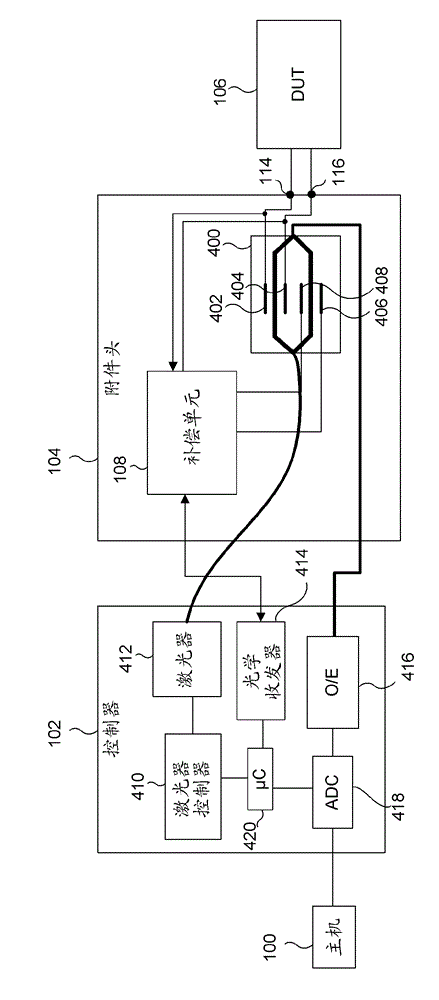
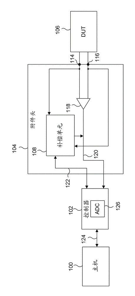
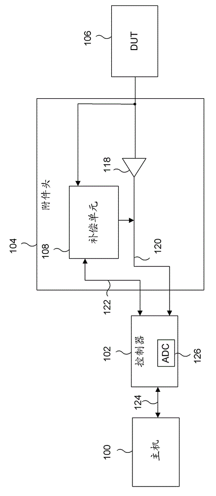
[0010] Sometimes, accessories attached to the DUT cannot be easily removed in order to calibrate or compensate the accessories. For example, accessories may be permanently mounted in a test fixture, soldered to the DUT, mounted in an inaccessible or remote location, in an environmental chamber, or in a hazardous location such as a location with high voltage. Therefore, in situations such as these, it is important to be able to calibrate or compensate the accessory without removing the accessory from the DUT.

[0011] Some embodiments of the disclosed technology enable the use of optical voltage sensors (as discussed in more detail below) to measure Electrical signals ranging from direct current (DC) to gigahertz (GHz). The output of an optical sensor is susceptible to changes in the environm...


PUM


Abstract

A test and measurement system including a device under test, an accessory, a controller and a test and measurement instrument. The accessory is connected to the device under test and includes a signal input to receive an input signal from the device under test, a compensation unit configured to apply a compensation signal internal to the accessory, and a signal output to output an output signal read from the device under test. The controller is connected to the accessory and includes one or more receivers to receive the input signal and the output signal from the accessory, and a microcontroller or correction circuit configured to compare the input signal and the output signal and in response to the comparison provide a compensation signal to the compensation unit.

Description

technical field [0001] The present disclosure relates to the field of electronic test and measurement instruments and their accessories. The disclosed technique specifically addresses the problem of dynamically compensating for probe accessories as they are used to make measurements for electronic instruments. Background technique [0002] Traditionally, compensating an accessory such as a probe in a test and measurement system involves removing the accessory from the device under test (DUT) and connecting the accessory to a calibration or compensation stimulus. Conventionally, a test and measurement system includes a host computer, a controller, and a device under test. The accessory attaches to the device under test and measures the signal from the device under test and sends it back to the host. However, in order to compensate the accessory, the accessory must be removed from the device under test and attached to a calibration / compensation stimulus typically located on ...

Claims


Application Information

Patent Timeline
Patent Type & Authority Applications(China)
IPC IPC(8): G01R1/00G01R35/00
CPCG01R31/00G01R1/06766G01R15/24G01R35/00
Inventor M.J.门德R.A.布曼
Owner TEKTRONIX INC
Features
  • R&D
  • Intellectual Property
  • Life Sciences
  • Materials
  • Tech Scout
  • Unparalleled Data Quality
  • Higher Quality Content
  • 60% Fewer Hallucinations
Learn More