Image Forming Apparatus

一种图像、调色剂像的技术,应用在图像形成装置领域,达到防止变色或者变形的效果

Active Publication Date: 2015-08-26
KONICA MINOLTA INC
View PDF6 Cites 2 Cited by
  • Summary
  • Abstract
  • Description
  • Claims
  • Application Information

AI Technical Summary

Problems solved by technology

[0004] However, the separation distance between the fixing surface side member and the rear side support member is usually about 2 to 3 mm, so if slack occurs in long paper, the fixing surface side member will come into contact.

Method used


Image

  • Image Forming Apparatus
  • Image Forming Apparatus
  • Image Forming Apparatus

Examples


Embodiment Construction

[0025] Hereinafter, embodiments of the present invention will be described in detail with reference to the drawings.

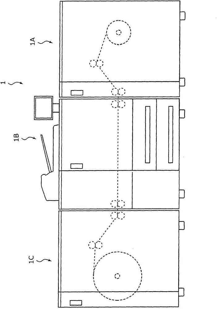
[0026] figure 1 It is a diagram showing an image forming apparatus 1 according to an embodiment of the present invention.

[0027] figure 1 The illustrated image forming apparatus 1 includes a paper feeding device 1A, an image forming apparatus main body 1B, and a winding device 1C.

[0028] The paper feeding device 1A stores long paper such as roll paper and continuous paper, and feeds the paper according to an instruction from the image forming apparatus main body 1B. The image forming apparatus main body 1B forms an image on a long sheet of paper supplied from the sheet feeding apparatus 1A. The winding device 1C winds a long sheet of paper that has been sent out after being imaged by the image forming apparatus main body 1B.

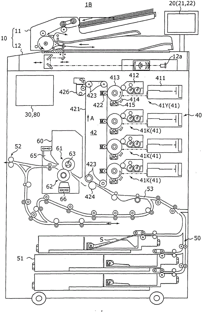
[0029] figure 2 It is a diagram showing the overall configuration of the image forming apparatus main body 1B. image 3 It i...


PUM


Abstract

An image forming apparatus (1) includes a sheet conveyance section (50) configured to convey a long sheet; an image forming section (40) configured to transfer a toner image to a long sheet; and a fixing section (60) configured to apply heat and pressure to a long sheet conveyed along a sheet feeding path at a fixing nip so as to fix a toner image. During cooling-down or warming-up of the fixing section (60), the sheet conveyance section (50) performs conveyance of a long sheet when the a fixing temperature of the fixing side member is higher than a predetermined idling temperature, and stops conveyance of a long sheet when the fixing temperature of the fixing side member is lower than the predetermined idling temperature.

Description

technical field [0001] The present invention relates to an electrophotographic image forming apparatus that forms an image on a long paper. Background technique [0002] Generally, in an image forming apparatus (printer, copying machine, facsimile machine, etc.) utilizing electrophotographic processing technology, a uniformly charged photoreceptor (such as a photoreceptor drum) is irradiated (exposed) with laser light based on image data. An electrostatic latent image is formed on the surface of the photoreceptor. Then, by supplying toner to the photoreceptor on which the electrostatic latent image has been formed, the electrostatic latent image is visualized to form a toner image. After the toner image is directly or indirectly transferred to the paper via an intermediate transfer body, it is heated and pressurized by a fixing device to form an image on the paper. [0003] In such an image forming apparatus, when long paper such as roll paper or continuous paper (continuo...

Claims


Application Information

Patent Timeline
Patent Type & Authority Applications(China)
IPC IPC(8): G03G15/00
CPCG03G15/6564G03G15/205
Inventor 深井省吾
Owner KONICA MINOLTA INC
Why Eureka
Try Eureka