
Transformer breather

The technology of a respirator and a transformer is applied to the transformer respirator. It can solve the problems of abnormal positive and negative pressure of transformer oil conservator, loss of protection function, pollution of transformer oil, etc., and achieve the effect of simple structure and reliable performance

Inactive Publication Date: 2015-08-26
DALIAN POWER SUPPLY COMPANY STATE GRID LIAONING ELECTRIC POWER +1
View PDF9 Cites 2 Cited by
  • Summary
  • Abstract
  • Description
  • Claims
  • Application Information

AI Technical Summary

Problems solved by technology

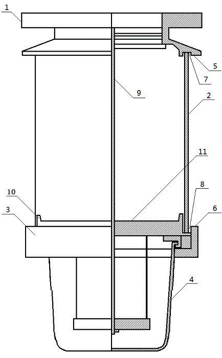
[0002] The height of the upper surface of the lower base (or "oil cup flange") of the glass cover of the existing transformer respirator is the same as the height of its outer periphery. The moisture on the edge keeps freezing and increasing. When the freezing height exceeds the height of the water barrier in the glass cover, if the seal between the glass cover and the base is not good, the melted water will seep into the glass cover due to the principle of the connector, not only It will flow into the oil cup through the breathing hole of the base to pollute the transformer oil, and will block the breathing hole due to freezing, thereby hindering the breathing function of the respirator, causing abnormal positive and negative pressures in the transformer oil conservator, losing the protection function and causing accidents

Method used


Image

  • Transformer breather
  • Transformer breather

Examples


Embodiment Construction

[0011] The present invention will be further described below in conjunction with accompanying drawing:

[0012] Such as figure 1 As shown, the present invention is composed of upper flange (1), glass cover (2), silica gel, base (3), oil cup (4) and the like. The outer periphery of the upper flange ⑴ and the base ⑶ are inlaid grooves ⑺ and ⑻ for the glass cover ⑵ on the inner side of the outer periphery ⑸ and ⑹. There is a sealing rubber pad in the groove, and the glass cover is inlaid between the upper flange and the base with built-in silica gel. An oil cup (4) is arranged at the lower part of the base, and a breathing hole through which the upper and lower parts are connected is arranged on the base. The above-mentioned components are connected as a whole by the through-hole screw ⑼.

[0013] Such as figure 2 As shown, the upper surface ⑾ of the base ⑶ provided with breathing holes is higher than the height of the outer periphery ⑹ of the base, and a water retaining edge...


PUM


Abstract

The invention relates to a transformer breather which comprises an upper flange, a glass cover, a silica gel, a base, an oil cup and the like. The transformer breather is characterized in that the height of the upper surface of the base is higher than that of the peripheral edge of the base, and a water retaining edge is further arranged on the upper surface of the base. Through the change on the base structure, moisture cannot flow into the breather, a breathing hole in the base can be prevented from being blocked by an ice layer, and under the conditions of humidity and low temperature, the breather can normally breathe and is ensured to play a protective function. The transformer breather is simple in structure and reliable in performance, and can be achieved by simply upgrading the traditional breather.

Description

technical field [0001] The invention relates to a safety protection device attached to a transformer, in particular to a transformer respirator. Background technique [0002] The height of the upper surface of the lower base (or "oil cup flange") of the glass cover of the existing transformer respirator is the same as the height of its outer periphery. The moisture on the edge keeps freezing and increasing. When the freezing height exceeds the height of the water barrier in the glass cover, if the seal between the glass cover and the base is not good, the melted water will seep into the glass cover due to the principle of the connector, not only It will flow into the oil cup through the breathing hole of the base to pollute the transformer oil, and will block the breathing hole due to freezing, thereby hindering the breathing function of the respirator, causing abnormal positive and negative pressures in the transformer oil conservator, losing the protection function and cau...

Claims


Application Information

Patent Timeline
Patent Type & Authority Applications(China)
IPC IPC(8): H01F27/14
Inventor 吕颜刚郭兆成黄鑫柳尚一迟福有郑文海陈琳
Owner DALIAN POWER SUPPLY COMPANY STATE GRID LIAONING ELECTRIC POWER
Learn More