
OLED array substrate, production method thereof, OLED display device

A technology for array substrates and manufacturing methods, which is applied in the direction of electrical components, electrical solid devices, circuits, etc., can solve the problems of reducing the area of ​​the opening area, occupying, and reducing the aperture ratio of OLED display devices, so as to improve uniformity and reduce IRdrop Effect

Active Publication Date: 2015-08-26
BOE TECH GRP CO LTD
View PDF5 Cites 10 Cited by
  • Summary
  • Abstract
  • Description
  • Claims
  • Application Information

AI Technical Summary

Problems solved by technology

The inventors found that in the prior art, the first electrode auxiliary line would occupy a certain area, resulting in a reduction in the area of ​​the opening area, thereby reducing the aperture ratio of the entire OLED display device

Method used


Image

  • OLED array substrate, production method thereof, OLED display device
  • OLED array substrate, production method thereof, OLED display device
  • OLED array substrate, production method thereof, OLED display device

Examples


Embodiment 1

[0050] An embodiment of the present invention provides an OLED array substrate, which can reduce the IR drop of the first electrode without reducing the aperture ratio of the OLED display device.

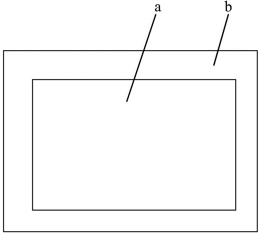
[0051] Specifically, such as figure 1 and figure 2 As shown, the OLED array substrate (hereinafter referred to as the array substrate) includes a plurality of first pixel definition layers 4, a first electrode 8, and a conductive layer 5 between the plurality of first pixel definition layers 4 and the first electrodes 8, Inside the display area a, the vertical projection of the plurality of first pixel definition layers 4 on the array substrate covers the vertical projection of the conductive layer 5 on the array substrate, and outside the display area b, the first electrode 8 and at least one conductive layer 5 are electrically connected connect. Exemplarily, the plurality of first pixel definition layers 4 in the embodiment of the present invention are arranged in a plane and c...

Embodiment 2

[0070] An embodiment of the present invention provides a method for manufacturing the OLED array substrate (hereinafter referred to as the array substrate) described in Embodiment 1. Specifically, the method includes: forming a plurality of first pixel definition layers 4; forming At least one conductive layer 5 and forms a first electrode 8 . Wherein, the conductive layer 5 is located between a plurality of first pixel definition layers 4 and the first electrodes 8; and inside the display area a, the vertical projection of the first pixel definition layer 4 on the array substrate covers the conductive layer 5 on the array substrate In the vertical projection of , the first electrode 8 is electrically connected to the conductive layer 5 outside the display area b.

[0071] Therefore, the array substrate manufactured by the above manufacturing method can reduce the IR drop of the first electrode 8 and improve the uniformity of the display screen of the OLED display device, and ...


PUM


Abstract

The invention discloses an OLED array substrate, a production method thereof and an OLED display device and belongs to the display technical field. With the OLED array substrate adopted, the IR drop of a first electrode can be reduced under the premise that the opening rate of the OLED display device is not decreased. The OLED array substrate comprises a first electrode and a plurality of first pixel defining layers. The OLED array substrate further comprising at least one electric conduction layer between the plurality of first pixel defining layers and the first electrode; inside a display area, the vertical projections of the plurality of first pixel defining layers on the array substrate cover the vertical projections of the electric conduction layers on the array substrate; and outside the display area, the first electrode is electrically connected with the at least one electric conduction layer.

Description

technical field [0001] The invention relates to the field of display technology, in particular to an OLED array substrate, a manufacturing method thereof, and an OLED display device. Background technique [0002] Organic Light Emitting Diode (OLED) display devices have the advantages of fast response speed, high contrast ratio, wide viewing angle, light and thin, power saving and low cost, and have attracted more and more attention. [0003] Specifically, the OLED display device includes an array substrate on which an OLED is formed, and the first electrode (usually a cathode) of the OLED is a bulk electrode covering the array substrate, usually made of conductive metal such as Mg and Ag. For a top-emitting OLED display device, the light emitted by the OLED is emitted from the first electrode, which requires a high transmittance of the first electrode. Therefore, the first electrode is usually very thin, so that the resistance of the first electrode is high, and the IR The ...

Claims


Application Information

Patent Timeline
Patent Type & Authority Applications(China)
IPC IPC(8): H01L27/32
CPCH10K59/122H10K59/131H10K71/00H10K59/80522H10K59/80518H10K50/818H10K50/824H10K59/124H10K59/1201H01L2224/48091H01L2224/48247
Inventor 高静
Owner BOE TECH GRP CO LTD
Learn More