A permanent magnet coupler with manual speed adjustment

A permanent magnet coupler and manual speed regulation technology, applied in the field of couplers, can solve problems such as high cost, low efficiency, and complex structure of the adjustment device

Active Publication Date: 2017-11-03
东营河太能源科技有限公司
View PDF4 Cites 0 Cited by
  • Summary
  • Abstract
  • Description
  • Claims
  • Application Information

AI Technical Summary

Problems solved by technology

[0005] Purpose of the invention: the present invention solves the problem of complex structure, high cost and low efficiency of the existing permanent magnetic coupler adjustment device

Method used


Image

  • A permanent magnet coupler with manual speed adjustment
  • A permanent magnet coupler with manual speed adjustment
  • A permanent magnet coupler with manual speed adjustment

Examples


Embodiment 1

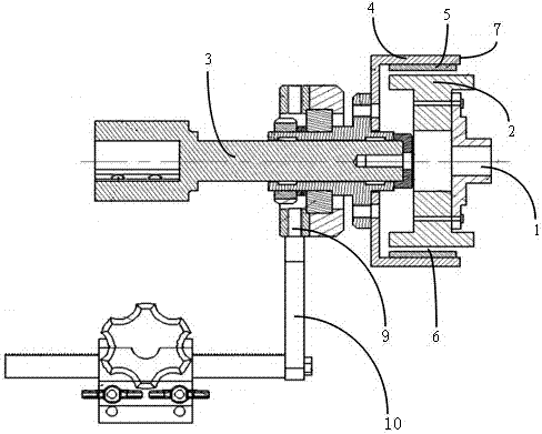
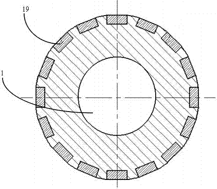
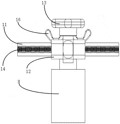
[0021] Such as figure 1 , figure 2 and image 3 As shown, a permanent magnet coupler with manual speed adjustment includes a permanent magnet coupler, the permanent magnet coupler includes a power part and a transmission part, and the power part includes a motor (not shown), and a motor shaft 1 Connected conductor column 2, the transmission part includes a transmission shaft 3, a magnet cylinder 4 arranged on the transmission shaft 3 that can rotate synchronously with the transmission shaft 3, and two permanent magnets 5 disposed inside the magnet cylinder 4, the conductor There is an air gap 6 between the post 2 and the permanent magnet 5, and the distance between the adjacent permanent magnets along the circumference of the magnet cylinder is the same, and the permanent magnet 5 arranged on the magnet cylinder 4 does not exceed its corresponding outer edge 7, and It includes a speed regulating device arranged in the transmission part of the permanent magnetic coupler. Th...

Embodiment 2

[0024] Such as figure 1 , figure 2 and image 3 As shown, a permanent magnet coupler with manual speed adjustment includes a permanent magnet coupler, the permanent magnet coupler includes a power part and a transmission part, and the power part includes a motor (not shown), and a motor shaft 1 Connected conductor column 2, the transmission part includes a transmission shaft 3, a magnet cylinder 4 arranged on the transmission shaft 3 that can rotate synchronously with the transmission shaft 3, and three permanent magnets 5 disposed inside the magnet cylinder 4, the conductor There is an air gap 6 between the post 2 and the permanent magnet 5, and the distance between the adjacent permanent magnets along the circumference of the magnet cylinder is the same, and the permanent magnet 5 arranged on the magnet cylinder 4 does not exceed its corresponding outer edge 7, and It includes a speed regulating device arranged in the transmission part of the permanent magnetic coupler. ...


PUM


Abstract

The present invention provides a permanent magnet coupler that can be manually adjusted in speed, including a permanent magnet coupler, the permanent magnet coupler includes a power part and a transmission part, the power part includes a motor, and a conductor column connected to the motor shaft. The transmission part includes a transmission shaft, a magnet cylinder connected to the transmission shaft, and at least two permanent magnets arranged inside the magnet cylinder. There is an air gap between the conductor posts and the permanent magnets. The distance from the cylinder circumference is the same. It also includes a speed regulating device arranged on the transmission part of the permanent magnet coupler, the speed regulating device includes a seat body, a support part fixedly connected with the transmission part, and a fixing groove provided on the seat body fixedly connected with the support part through a fixed rod The inner cylindrical adjustment rack, the hand-twist handle is arranged on one side of the fixing groove, and is adapted to connect with the cylindrical straight tooth part of the cylindrical adjustment rack. By adopting the design of the invention, the function of indirectly adjusting the rotating speed of the transmission part can be realized by manually adjusting the hand-twist handle, which is practical.

Description

technical field [0001] The invention relates to a coupler, in particular to a permanent magnet coupler with manual speed adjustment. Background technique [0002] The permanent magnet speed governor consists of three parts: conductor disk, magnet disk, motor and load. Wherein, the conductor disc is installed on the motor, and the magnet disc is installed on the load (fan, water pump, etc.), and there is no mechanical connection between the conductor disc and the magnet disc, which is an air gap; permanent magnets are installed on the magnet disc. When the motor rotates, the conductor disc of the drive part rotates, and the conductor disc moves relative to the magnet, and an induced current is generated in the conductor disc, which is then converted into an induced magnetic field. The induced magnetic field interacts with the magnetic field generated by the original permanent magnet to drive the load to rotate, realizing The effect of torque transmission through the air gap....

Claims


Application Information

Patent Timeline
Patent Type & Authority Patents(China)
IPC IPC(8): H02K51/00
Inventor 李志伟
Owner 东营河太能源科技有限公司
Why Eureka
Try Eureka