Vehicle-mounted rut real-time detection system and detection method

A technology of real-time detection and detection method, applied in the directions of roads, road repair, roads, etc., can solve the problems of asynchrony, waste of time, etc., and achieve the effect of high integration, high system integration, and easy real-time adjustment.

Inactive Publication Date: 2015-09-02
SHANGHAI YISEN INFORMATION TECH
View PDF7 Cites 4 Cited by
  • Summary
  • Abstract
  • Description
  • Claims
  • Application Information

AI Technical Summary

Problems solved by technology

[0005] In view of the above technical problems, the present invention discloses a real-time vehicle rut detection system and detection method, which solves the problem that the data of rut detection in the prior art needs to be stored in the hard disk and then brought back to th

Method used


Image

  • Vehicle-mounted rut real-time detection system and detection method
  • Vehicle-mounted rut real-time detection system and detection method
  • Vehicle-mounted rut real-time detection system and detection method

Examples


Example Embodiment

[0033] Example 1

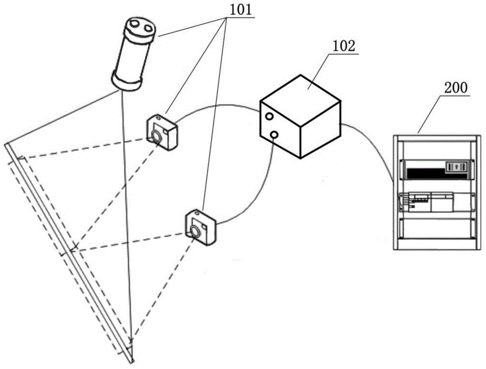
[0034] The invention provides a vehicle-mounted rut detection system, which combines figure 1 with figure 2 It can be seen that the vehicle-mounted rut real-time detection system includes a first system 100 installed on the detection vehicle and a second system 200 installed outside the detection vehicle.

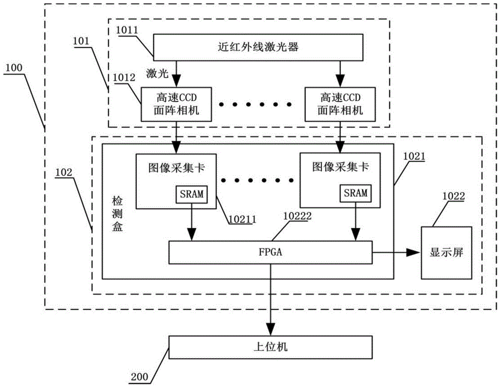
[0035] The first system 100 includes an image acquisition device 101 for collecting road rut image information and a real-time rut image information analysis device 102 that receives the rut image information collected by the image acquisition device and performs storage, analysis, and processing. The image acquisition device 101 includes a near-infrared laser 1011 that emits laser light to irradiate the road surface, and a plurality of high-speed CCD (charge coupled device) area scan cameras 1012 that irradiate the near-infrared laser 1011 on the road surface. The near-infrared laser 1011 is fixed above the rear of the vehicle to be inspected. The beam angl...

Example Embodiment

[0039] Example 2

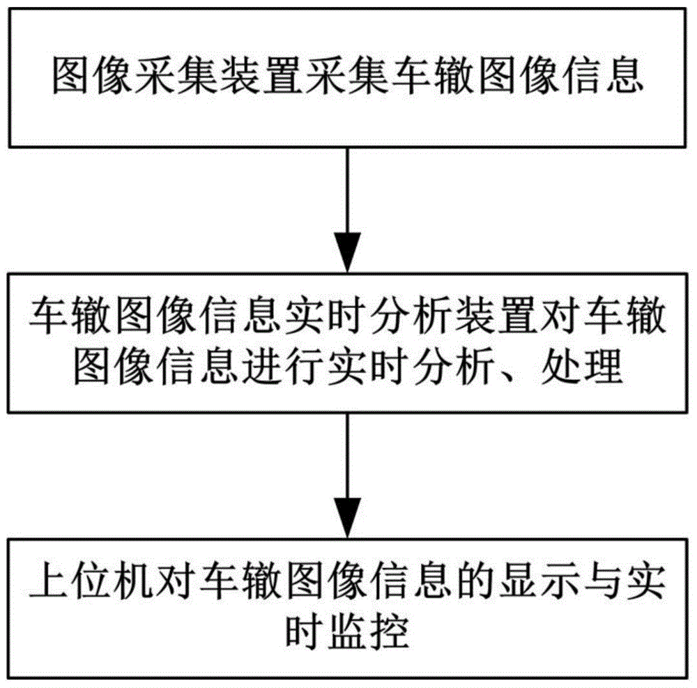
[0040] This embodiment provides a detection method for rut detection using the rut real-time detection system in embodiment 1, as image 3 As shown, it mainly includes the following steps:

[0041] Step 1) The image acquisition device collects rut ​​image information: the near-infrared laser emits laser light to irradiate the road surface, and multiple high-speed CCD area cameras simultaneously photograph the road surface irradiated by the near-infrared laser laser to collect rut image information;

[0042] Step 2) The rut image information real-time analysis device analyzes and processes the rut image information collected by the multiple high-speed CCD area cameras: each of the high-speed CCD area cameras sends the rut image information obtained by photographing to its corresponding One of the image capture cards, the image capture card stores the received rut image information in the SRAM, and the FPGA reads the rut image information stored in the SRAM and ana...


PUM


Abstract

The invention discloses a vehicle-mounted rut real-time detection system and detection method. The detection system comprises a first system mounted on a detection vehicle and a second system arranged outside the detection vehicle, wherein the first system comprises an image acquisition device and a rut image information real-time analysis device; the image acquisition device is used for acquiring pavement rut image information; the rut image information real-time analysis device is used for saving, analyzing and processing the rut image information acquired by the image acquisition device, and comprises a detection box and a display screen; the detection box integrates the FPGA and a plurality of image acquisition cards; a high-speed CCD area-array camera sends the rut image information obtained through shooting to the image acquisition cards; the image acquisition cards receive and save the rut image information; the FPGA reads the rut image information saved in the image acquisition cards for analysis and processing; the display screen is used for displaying the rut image information processed by the FPGA. The detection system and detection method have the advantages of being high in integration level, efficiency, visibility measuring accuracy, and real-time synchronicity.

Description

technical field [0001] The invention relates to the field of road detection, in particular to a vehicle-mounted rut real-time detection system and detection method. Background technique [0002] Rutting refers to the longitudinal strip-shaped grooves on the road surface along the driving track, which are caused by the flow deformation, wear and subsidence of vehicles on the road. Rutting directly endangers the quality of the road surface, reduces the service life of the road surface, and shortens the maintenance cycle; in addition, during high-speed driving, if the direction is turned slightly, accidents that are difficult to deal with are prone to occur. Therefore, it is very necessary to regularly detect and repair road ruts. [0003] At present, two green or infrared lasers are mostly used in the rut detection system. Due to the high power requirements of the green laser, a 532nm green semiconductor line laser is currently used. Due to product technology and quality reas...

Claims


Application Information

Patent Timeline
IPC IPC(8): E01C23/01
Inventor 陈新荣
Owner SHANGHAI YISEN INFORMATION TECH
Why Eureka
Try Eureka