Substrate bonding method buried with Bragg reflector having high reflectivity

A Bragg reflector, high reflectivity technology, applied in the structure of optical resonator cavity, electrical components, semiconductor/solid-state device manufacturing, etc., can solve the problem of mirror surface roughness and cannot be directly bonded

Inactive Publication Date: 2005-09-28
INST OF SEMICONDUCTORS - CHINESE ACAD OF SCI
View PDF1 Cites 4 Cited by
  • Summary
  • Abstract
  • Description
  • Claims
  • Application Information

AI Technical Summary

Problems solved by technology

[0005] The present invention discloses a new direct bonding method of high reflectivity Bragg reflector, which effectively solves the problem of SiO 2 The surface roughness of the / Si mirror cannot be directly bonded. At the same time, there is no need to introduce a polishing process, which reduces the process cost and process difficulty.

Method used


Image

  • Substrate bonding method buried with Bragg reflector having high reflectivity
  • Substrate bonding method buried with Bragg reflector having high reflectivity
  • Substrate bonding method buried with Bragg reflector having high reflectivity

Examples


Embodiment Construction

[0024] see Figure 1A ~ Figure 1E , this embodiment discloses a schematic diagram of a process for manufacturing a high-reflectivity substrate buried with a high-reflectivity Bragg reflector using the substrate bonding technology disclosed in the present invention. Its process steps include:

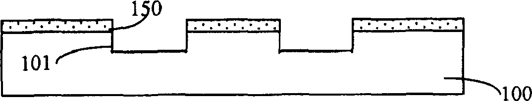
[0025] a) mask photolithography on the first substrate 100, etch out the groove 101, and keep the photoresist 150 ( Figure 1A middle);

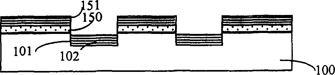
[0026] b) growing a high-reflectivity Bragg mirror 102 in the trench 101 ( Figure 1B middle);

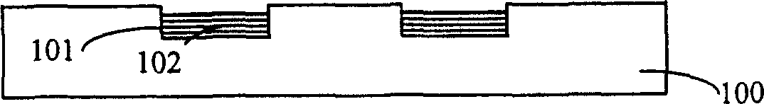
[0027] c) The Bragg reflector 151 and the photoresist 150 outside the trench 101 are stripped off by stripping with glue, and the reflector 102 in the trench is retained ( Figure 1C middle);

[0028] d) performing a chemical cleaning treatment on the first substrate 100 and the second substrate 110, and then bonding them together at room temperature for pre-bonding ( Figure 1D middle);

[0029] e) Carry out high temperature thermal annealing treatme...


PUM

PropertyMeasurementUnit
surface roughnessaaaaaaaaaa

Abstract

The present invention relates to a method for bonding substrate with buried high-reflectivity Bragg reflector. Said method includes the following steps: a). on first substrate masking and photoetching to obtain etch-out channel; b). in the channel growing high-reflectivity Bragg reflector by carrying photoresist; c). adopting photoresist-carrying stripping method to remove photoresist and reflector outside of channel; and d). cleaning first substrate and second substrate, and bonding them together.

Description

technical field [0001] The invention relates to a substrate bonding technology. In particular, it relates to a substrate bonding method buried with a high-reflectivity Bragg reflector, so as to manufacture a narrow-band high-efficiency resonant cavity-enhanced detector, especially a silicon-based high-efficiency high-speed resonant cavity-enhanced detector. Background technique [0002] With the advent of the information age, the global communication traffic is increasing rapidly, and the development of communication networks is facing unprecedented opportunities and challenges. As early as the 1960s, optical fiber communication began to develop. Single-channel optical fiber communication can no longer meet the increasing demand for communication traffic. People began to require simultaneous transmission of multiple wavelengths of optical signals in one optical fiber. This is wavelength division multiplexing (WDM) WDM) technology, the maturity of erbium-doped fiber amplifie...

Claims


Application Information

Patent Timeline
Patent Type & Authority Applications(China)
IPC IPC(8): H01L21/00H01S5/10
Inventor 毛容伟滕学公王启明
Owner INST OF SEMICONDUCTORS - CHINESE ACAD OF SCI
Why Eureka
Try Eureka