Releasing apparatus

A technology of losing hands and sets, applied in wellbore/well components, earthwork drilling, etc., can solve the problems of construction failure, inability to lose hands, economic losses, etc., to achieve reliable loss of hands, significant economic benefits, and improve the success rate of construction Effect

Active Publication Date: 2015-09-02
山东兆鑫石油工具有限公司
View PDF8 Cites 3 Cited by
  • Summary
  • Abstract
  • Description
  • Claims
  • Application Information

AI Technical Summary

Problems solved by technology

There are some deficiencies in the current throwing device. The prominent problem is that the throwing mechanism will fail after being buried by sand and sundries, and the problem of being unable to throw away will appear, resulting in construction failure and heavy economic losses.

Method used


Image

  • Releasing apparatus

Examples


Embodiment Construction

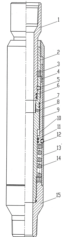
[0007] Embodiments of the present invention will be described below in conjunction with the accompanying drawings.

[0008] As shown in the figure, the embodiment of the present invention includes an upper joint 1, a lower joint 2, a lock block 3, a shear nail 5, an upper sealing ring 6, a middle sealing ring 7, a release pipe 9, and a lower sealing ring 11 , unlock the shear nail 12, jacket 13, spring 14, lower joint 15, the lower part of the upper joint 1 is installed in the upper part of the lower joint 2, and the shear nail 5 is installed on the upper joint 1 and the lower joint 2 , there is a lock groove on the outer wall of the upper connector 1, and a lock window on the lower connector 2, the lock window corresponds to the lock groove, and the lock block 3 is placed in the lock window, and the inner wall of the lock block 3 enters the upper connector 1 In the lock groove on the outer wall, the upper and lower joints 1 and 2 are locked together and can bear the axial for...


PUM


Abstract

The invention discloses a releasing apparatus. The lower part of a releasing upper joint is mounted inside the upper part of a releasing lower joint. A releasing shear pin is mounted on the releasing upper and lower joints. A locking slot of the releasing upper joint corresponds to a locking window of the releasing lower joint, and a locking block is disposed inside the locking window. Upper sealing rings are mounted between the releasing upper joint and the releasing lower joint. The releasing lower joint is sleeved with a releasing pipe and springs, and the releasing pipe encases the locking block. The middle part of the releasing lower joint is provided with a connecting hole. Middle sealing rings and lower sealing rings are mounted between the releasing lower joint and an outer sleeve. The middle sealing rings are arranged above the connecting hole, and the lower sealing rings are arranged below the connecting hole. A annular space is formed between the releasing lower joint and the outer sleeve due to diameter difference, and is located between the middle sealing rings and the lower sealing rings. The lower part of the releasing lower joint is connected to the upper part of a lower joint. The releasing pipe is internally provided with a releasing groove. The outer sleeve sleeves the releasing pipe. The upper part of the outer sleeve is connected to the upper part of the releasing lower joint. An unlocking shear pin is arranged on the releasing pipe and the outer sleeve. According to the invention, releasing operation can be reliably carried out, and the construction success rate can be improved.

Description

technical field [0001] The invention is downhole equipment used for oilfield operations, and is a hands-free device. Background technique [0002] When implementing layered acid fracturing and layered water plugging operations, it is necessary to divide the downhole tool into two parts in the well, one part is brought up the well, and the other part is left in the tool in the well. A tool that divides a downhole tool into two parts in the well is called a hands-off device. There are some deficiencies in the current throwing device. The outstanding problem is that the throwing mechanism will fail after being buried by sand and sundries, and the problem of being unable to throw away occurs, resulting in construction failure and significant economic losses. Contents of the invention [0003] The purpose of the present invention is to design a hands-off device so that it can reliably lose hands and improve the success rate of construction. [0004] The purpose of the present...

Claims


Application Information

Patent Timeline
Patent Type & Authority Applications(China)
IPC IPC(8): E21B23/00
Inventor 曲绍坤马宝龙曲哲杨永刚黄芳玉荣雷杜博
Owner 山东兆鑫石油工具有限公司
Why Eureka
Try Eureka