Pipeline connector

A technology for pipelines and joint sleeves, applied in mechanical equipment, couplings, etc., can solve problems such as affecting service life, medium leakage, poor reliability, etc., and achieve the effects of convenient installation and disassembly, good sealing and long service life.

Inactive Publication Date: 2015-09-02
LIUZHOU CITY QIANYANG MACHINERY & ELECTRIC
View PDF5 Cites 2 Cited by
  • Summary
  • Abstract
  • Description
  • Claims
  • Application Information

AI Technical Summary

Problems solved by technology

[0003] The technical problem to be solved by the present invention is to provide a pipeline joint, which can solve the problems of complex and cumbersome connection operations of existing pipelines, uncontrollable flow rate of conveying medium, poor reliability, prone to medium leakage, and affecting service life.

Method used


Image

  • Pipeline connector

Examples


Embodiment Construction

[0011] The present invention will be described in further detail below in conjunction with accompanying drawing embodiment:

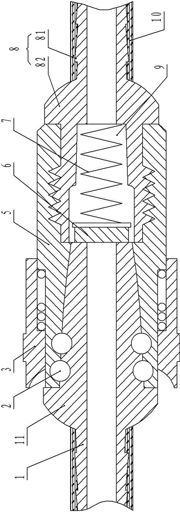
[0012] figure 1 The shown pipeline joint includes a pipe seat cover 5, a first joint cover 1 and a second joint cover 8 are respectively inserted at both ends of the pipe seat cover 5, and a The steel ball 2, the second joint sleeve 8 are threadedly connected with the pipe seat sleeve 5; The other end of the outer wall is provided with a tapered convex ring 81, and is connected with the pipeline; the second joint sleeve 8 is provided with a valve chamber 9 connected to the through hole, the second joint sleeve 8 and the first joint sleeve 1 A spool 6 is arranged in the valve cavity 9 at the butt joint end, the spool 6 is connected with the spring 7, and the other end of the spring 7 is fixed on the inner wall of the valve cavity 9 away from the spool 6; the first joint sleeve 1 and the second joint sleeve 8 The outer walls of the pipe seat cover 5 are...


PUM


Abstract

The invention discloses a pipeline connector and belongs to the technical field of connecting pipe fittings. The pipeline connector comprises a base sleeve. A first connector sleeve and a second connector sleeve are respectively inserted to two ends of the base sleeve, the through holes of the first connector sleeve and the second connector sleeve are coaxial, the tips of the first connector sleeve and the second connector sleeve are in butt joint, and the other ends of the first connector sleeve and the second connector sleeve are connected with a pipeline. A valve cavity communicated with the corresponding through hole is formed in the second connector sleeve, and a valve element connected with the inner wall of the valve cavity through a spring is disposed in the valve cavity at a position corresponding to the through hole. The outer walls of the first connector sleeve and the second connector sleeve are provided with annular bosses respective abutted against two ends of the base sleeve. A drop-proof sleeve is disposed outside the base sleeve. By the pipeline connector, the problems that existing pipeline connection is complex, the flow of conveying media cannot be controlled, reliability is poor, medium leakage easily occurs, and service life is affected.

Description

technical field [0001] The invention relates to the technical field of connecting pipe fittings, in particular to a joint used for connecting pipelines. Background technique [0002] Pipeline joints are a necessary part for the connection of medium conveying pipelines. The existing pipeline joints use metal pipe seat sleeves or hard plastic pipe seat sleeves with pipelines at both ends, and use bonding materials or heating to connect them; but This connection method has the following problems: the bonding operation is complex and cumbersome, and the flow rate of the conveying medium cannot be controlled, the reliability is poor, the medium is prone to leakage, and the service life is affected. Contents of the invention [0003] The technical problem to be solved by the present invention is to provide a pipeline joint, which can solve the problems of complex and cumbersome connection operations of existing pipelines, uncontrollable flow rate of conveying medium, poor reliab...

Claims


Application Information

Patent Timeline
Patent Type & Authority Applications(China)
IPC IPC(8): F16L37/40
CPCF16L37/40
Inventor 谢绪金
Owner LIUZHOU CITY QIANYANG MACHINERY & ELECTRIC
Why Eureka
Try Eureka