Complex protection device

A protection device and fuse technology, applied in emergency protection devices, emergency protection circuit devices, circuit devices, etc., can solve problems such as being difficult to cope with various environments, unsuitable for high power, and weak durability of protection devices, achieving simplified structure, Effects of improved thermal characteristics and reduced disconnection time

Active Publication Date: 2015-09-02
SMART ELECTRONICS CO LTD
View PDF9 Cites 4 Cited by
  • Summary
  • Abstract
  • Description
  • Claims
  • Application Information

AI Technical Summary

Problems solved by technology

[0007] Furthermore, when the adhesive resistor 2 is used, the protection device has weak durability, is not suitable for high power application, and is difficult to cope with various environments

Method used


Image

  • Complex protection device
  • Complex protection device
  • Complex protection device

Examples


Embodiment Construction

[0093] Hereinafter, preferred embodiments of the present invention will be described in detail with reference to the accompanying drawings.

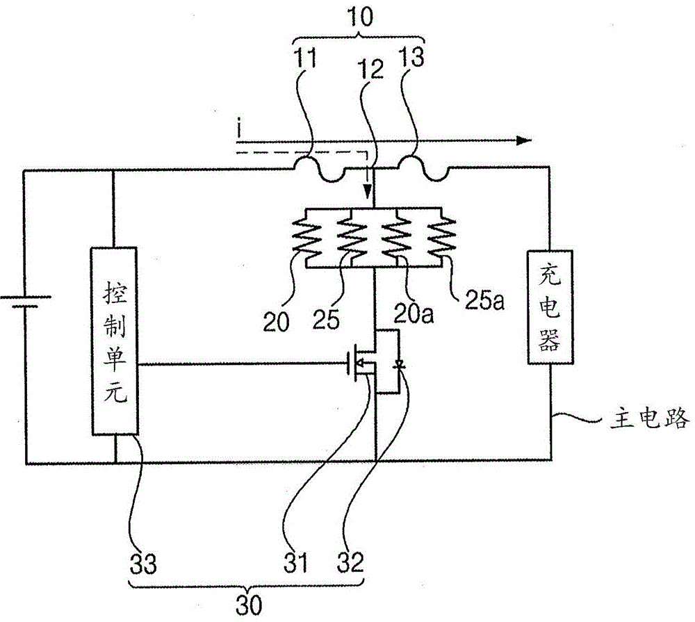
[0094] Please refer to figure 1 , according to the composite protection device of the present invention, protects the elements connected to the main circuit in an abnormal state by disconnecting the fusible element 10 connected to the main circuit.

[0095] The type of the main circuit of the composite protection device according to the present invention is not limited, for example, the main circuit may be a charging circuit for charging a battery.

[0096] The fusible element 10 is connected to a battery, and a charger and the fusible element 10 are connected to the main circuit.

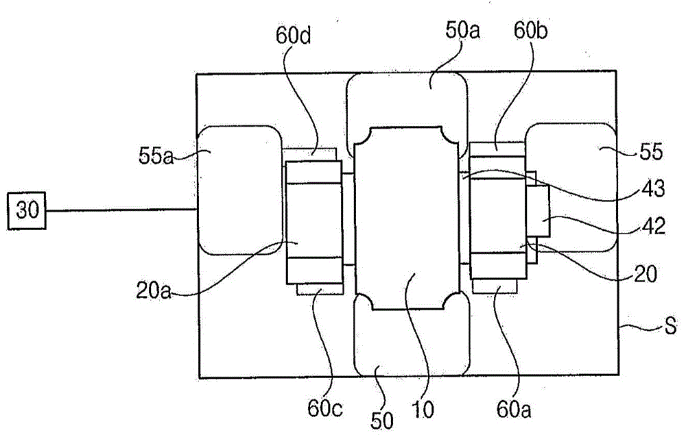
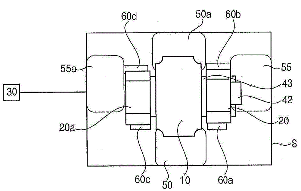
[0097] In detail, a plurality of resistance elements 20 , 20 a , 25 , 25 a connected to the fusible element 10 and a switching element 30 connected to these resistance elements 20 , 20 a , 25 , 25 a may be provided in the main circuit.

[0098] The switchi...


PUM


Abstract

Disclosed is a complex protection device including a substrate, fuse terminals provided on the substrate, first resistive terminals provided on the substrate so as to be separated from the fuse terminals, second resistive terminals provided on the substrate opposite to the first resistive terminals across the fuse terminals, a fusible element connected to the fuse terminals, a first surface-mounted resistive element connected to the first resistive terminals, a second surface-mounted resistive element connected to the second resistive terminals, at least one printed resistive element connected to at least one of the first resistive terminals and the second resistive terminals and connected to at least one of the first surface-mounted resistive element and the second surface-mounted resistive element, and a switching element controlling flow of current to the first and second surface-mounted resistive elements and the at least one printed resistive element if overvoltage is applied.

Description

technical field [0001] The present invention relates to a composite protection device, more specifically a composite protection device provided with both surface mounted resistive elements and printed resistive elements, and whereby a circuit and circuit elements provided on the circuit are protected against excessive voltage And excessive current, the printed resistance element is arranged under the surface mount resistance element, so the miniaturization of the product can be achieved. Background technique [0002] A non-recovery type protective device that operates in response to overheating generated by excessive current flow of the protective device or ambient temperature, the non-recovery type protective device operates at a specified temperature and shuts off the electronic circuit. For example, there is a protector device that heats a resistor in response to abnormality detected in a signal current of a device, and operates a fuse element using the generated heat. ...

Claims


Application Information

Patent Timeline
Patent Type & Authority Applications(China)
IPC IPC(8): H01H85/046H02H3/08H02H3/20
CPCH02H9/044
Inventor 姜斗园金炫昌金桄范尹生守权赫帝
Owner SMART ELECTRONICS CO LTD
Why Eureka
Try Eureka