Electric connector

A technology of electrical connectors and grounding parts, which is applied in the direction of connection, fixed connection, and parts of connection devices, etc., can solve the problems that cannot meet the signal transmission rate and signal integrity, and achieve high-speed transmission, stable fixation, and signal crosstalk. Reduced effect

Active Publication Date: 2015-09-02
MOLEX INC
View PDF13 Cites 3 Cited by
  • Summary
  • Abstract
  • Description
  • Claims
  • Application Information

AI Technical Summary

Problems solved by technology

[0005] In addition, the above three patent applications use different technical means to reduce signal crosstalk, but the technical means d

Method used


Image

  • Electric connector
  • Electric connector
  • Electric connector

Examples


Embodiment Construction

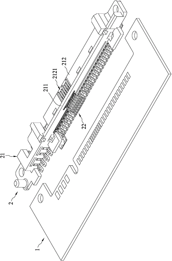
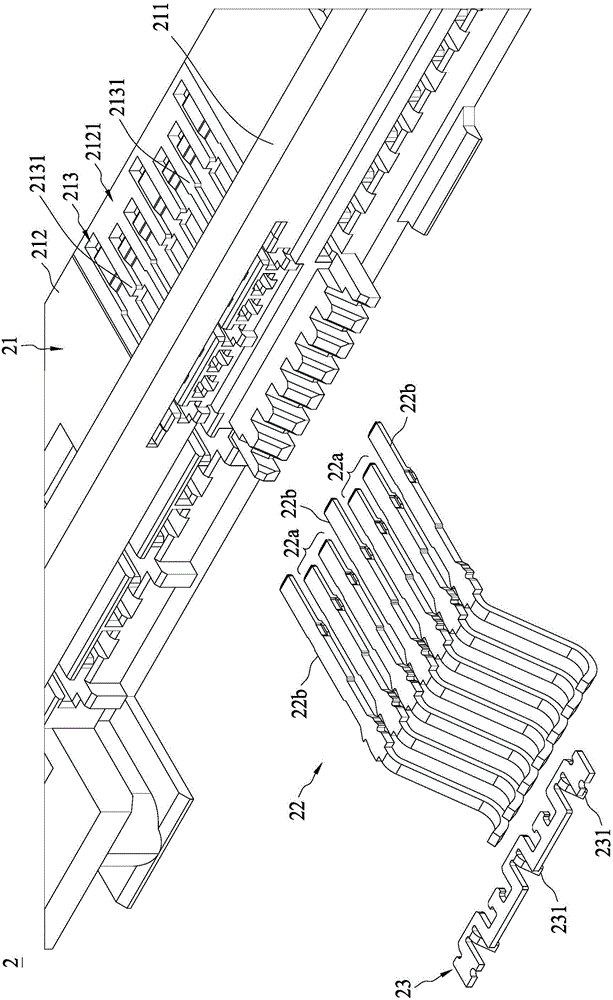
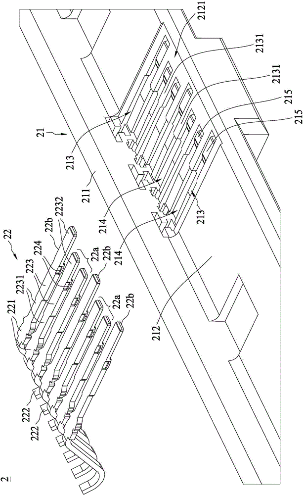
[0061] refer to Figure 1 to Figure 3As shown, the electrical connector 2 can be arranged on the circuit board 1 and connected to a docking device. The electrical connector 2 includes an elongated insulating body 21 and at least a first set of terminals 22 including a plurality of terminals (22a and 22b). The insulating body 21 includes a base 211 , a tongue 212 and a plurality of terminal grooves 213 . The tongue 212 protrudes from the base 211 . One side of the tongue 212 is provided with at least one first tongue portion 2121 . The plurality of terminal slots 213 correspond to the first group of terminals 22 . A plurality of terminal slots 213 are formed on the insulating body 21 and extend to the first tongue portion 2121 . On the first tongue portion 2121 , there are partition walls 2131 between the plurality of terminal slots 213 ; or two adjacent terminal slots 213 are at least partially separated by a partition wall 2131 .

[0062] refer to figure 2 and image ...


PUM


Abstract

An electric connector comprises an insulating body, signal terminals and grounding terminals respectively located on the two sides of the signal terminals. The insulating body comprises a tongue plate and a plurality of terminal grooves. The terminal grooves extend to the tongue plate. Spacing wall bodies are arranged among the terminal grooves. The signal terminals and the grounding terminals are respectively arranged in the terminal grooves. Each terminal comprises a flat contact part extending to the tongue plate and exposed on the tongue plate, and a holding projection. The flat contact part of each terminal comprises a thick segment and a thinned segment extending from the tail end of the thick segment. The holding projection of each terminal is arranged beside the intersection of the thick segment and the thinned segment and fixed with the inner wall of the corresponding terminal groove in an interference way. Grooves are arranged on the spacing wall bodies among each grounding terminal and the adjacent signal terminal so that the side edges of each grounding terminal and the adjacent signal terminal can be mutually exposed.

Description

technical field [0001] The invention relates to an electrical connector. Background technique [0002] Chinese patent application No. CN201120275305.5 (corresponding application No. 100127952 in Taiwan, China) discloses an electrical connector, which includes a first insulating body, a plurality of conductive terminals and a first housing. The first shell covers the outside of the first insulating body. The insulating body has a tongue plate and a plurality of holding grooves arranged on the tongue plate. The conductive terminal includes a contact portion and a main body extending from the contact portion, wherein the main body is fixed in the holding groove. The thickness of the contact part is thinner than that of the main part, so as to avoid the sudden change of impedance at the butt joint. However, due to the thinner thickness, the rigidity of the contact portion is weak, and the close contact between the contact portion of the conductive terminal and the terminal of...

Claims


Application Information

Patent Timeline
IPC IPC(8): H01R13/02H01R13/213H01R13/652H01R13/6464H01R13/40H01R12/51
CPCH01R12/51H01R13/02H01R13/213H01R13/40H01R13/6464H01R13/652
Inventor 朱章添蔡伟德
Owner MOLEX INC
Why Eureka
Try Eureka